Using ADAU1701 GPIO pins to switch multiplexer inputs
Hello,
I have GPIO pin configured as 'Input GPIO Debounce.' On my board, I have this pin pulled down.
All is fine if I connect this pin to an Adjustable Gain block with external control. Toggeling the GPIO state to HIGH, passes the audio signal
while it blocks/mutes the audio when the GPIO pin is pulled LOW.
When I connect the GPIO pin to an Index selectable Multiplexer with SW slew, I expected that it would switch the inputs appearing at the block's output pin when I toggle the state of the GPIO pin.
But it does not.
What could be the reason? For the multiplexer block, does the input GPIO pin need conversio to another number format?
Any help would be appriciated. Thank you!
Audio Signal Processors
Audio Products
software
SigmaDSP v4.7
SigmaDSP Audio Processors
adau1701
Show More
Hello KKSL,
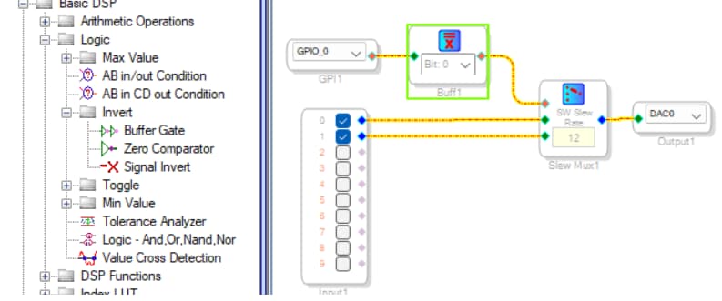
Just as you said, the issue has to do with the SigmaDSP number formats. The GPIO Input Block outputs a 1.0 decimal (5.23 format) number when its associated MP pin is brought high. This is quite compatible with the External Volume Control, which interprets this as a call for unity gain. On the other hand, the MUX expects an integer (Bit 0, or 28.0 format) control input, according to the desired switch position starting at zero. A direct connection from the GPIO to the MUX control input provides a number that's (2^23) times larger than what it wants to see. The result is silence or worse. To fix this, insert a Buffer Gate between the GPIO and the MUX control input, as shown below:
Best regards,
Bob
As always, you saved my day.
Thank you!
Please log in to reply.