Subwoofer DSP problem. Unstable Output with larger input
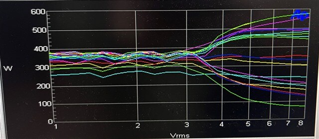
Hello, I am using sigma studio 4.6 to design a DSP for a subwoofer amplifier. My question mainly surrounds the limiter design. I am running into an issue where the limiter stops working correctly when the amp receives a large input voltage. The limiter works correctly up until about 3V RCA input. The issue we encountered can be seen in the attached image. Each line represents a frequency tested. Frequencies from 20Hz to 160Hz were tested in 10Hz increments. We found that with an input of over ~3V RMS, the output would either be overdriven or under driven. It appears that 20Hz-50Hz and 110Hz-140Hz would lose power above 3V input, while 60Hz-100Hz and 150-160Hz would overdrive the output. This issue seems to be frequency dependent. I tried to modify the limiter, but this did not resolve the issue. Also attached is the DSP project. Thanks
ADAU1761 Outside Tuning HP 12P_EQ_230824_17Hz 10dB.dspproj
Edit Notes
Photo edit
[edited by: RyanP at 3:37 PM (GMT -4) on 28 Aug 2023]
software
ada176x
Sigma Studio 4.6
ada176
ada1761
ADI North America will be on summer shutdown starting August 24, 2023; perhaps another community member can assist you until our return on September 5th.
Hello Ryan,
I am not sure where to start here. I did download your project and used the Audio Precision to make measurements.
First thing I need to point out is that the Max single ended line input voltage is 1.0Vrms. So if you are putting in 3Vrms you are clipping the "bleep" out of it. I verified that with the audio precision. The waveform looks quite ugly because the filters react to the high frequency content of the clipped signal.
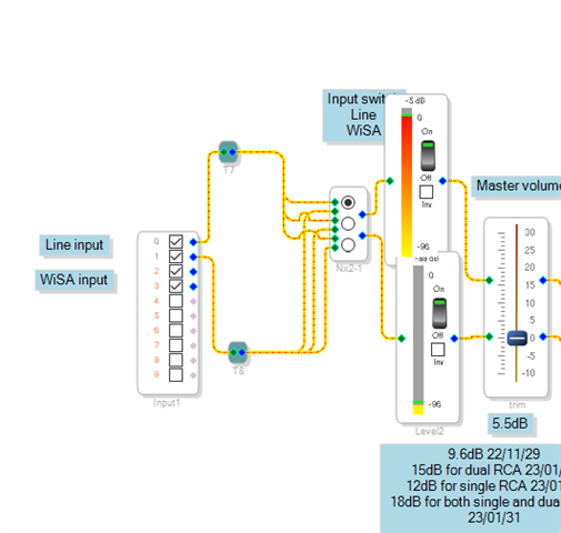
with your project, you have no way to verify that the input level is where it should be expected and likewise, the output level. You are running blind in your project. I suggest you put in some meters so you can see what the levels are within the DSP. This is what I did.
I was putting in a 1Vrms signal and you can see it is reading around -5dB which is a couple of dB clear of clipping. The specification has a bit of margin before it actually clips. The meters read RMS so the peak signal that would be 0dBFS for the 24 bit signal will read -3dB on the meter.
I do not know why you are combining two channels in some places and not others and you only have one mono output which makes sense for a subwoofer. But, you do not have the input setup for stereo to combine the low end of the two channels. But that is another discussion.
Then within the schematic you are adding a lot of gain. You were reducing the input level by 6dB in the analog input stage then boosting 5.5dB as soon as you get into the DSP core. That is not good gain structure.
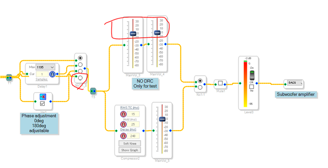
Then I added a meter on the very output so I can see what is going out of the core.
The level controls for bypassing the DRC had over +10dB of boost on one and the other was around 6dB of boost. This was also causing some significant clipping.
You can see I circled one additional setting I added to the MUX. This is connected to the output of the gain control right at the input so it is a bypass of all the EQs and everything else in the project.
I set the dual gain controls to 0dB and as you can see the signal out is slightly clipped. It is reading -2dB and I can see the clipped signal on a scope. This is due to the EQ along the path to get here. If I bypass the EQs the clipping goes away. But, interestingly, if I engage the DRC the clipping goes away so it is doing its job.
I hope you can see that these are your windows into the system. It is a powerful tool and you have been running blind.
By the way, the EQ boost is understandable and to be expected. It is the reason for some sort of DRC to guard against clipping the output.
Now,, on to the DRC.
You had a makeup gain boost after the DRC. I guess you could do that but it is not a great idea and it is best to just set the curve to do what you need to prevent clipping.
The compressor you chose is a good one and it sounds good. It is just not great for use as your final limiter before the output.
It is an RMS compressor not really a limiter. It was an attack time so peaks WILL get by and clip. You had the time constants set pretty close but not perfect for the low frequencies you are dealing with. To keep the gain from changing within one waveform and causing distortion, I recommend using a hold time and release time combination that is around three times longer than the period of the lowest frequency. In this case we could say 20Hz. 20Hz is a 50ms period so I would have at least 150ms and you did good there. You have the hold time of 25ms which is a little short but then the release time is 248ms. So that is good and long. Basically, with a 20Hz wave it will start to increase the gain during the period of one wave. But not too bad because you did set the decay time really long. It might not be all that audible.
However, the attack time of 15ms is not good at all.
What I recommend is to use a limiter that has instant attack time and then use a long hold and release. You did use a full range version and I would use a full range version of a limiter.
There is a lot to absorb here.
We can continue the discussion later.
Dave T
Please log in to reply.