ADAU1467 Schematic Review
Hello, could I please get some schematic design review comments on the attached schematic snippet?
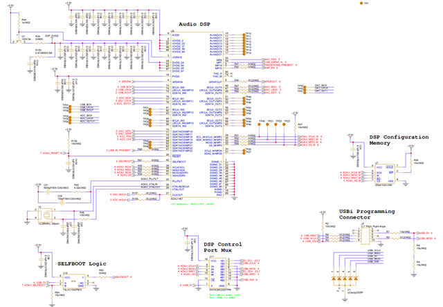
My intention is for SPI EEPROM self-boot normally, but use the U10 NOR gate to disable SELFBOOT if either USBi debug dongle is present or if MCU sets ADAU_SELFBOOT net high.
My other intention is to use the U11 mux to either connect MCU I2C or the USBi connector to the ADAU1467 slave I2C/SPI port.
The J3 USBi connector is exposed for external use, hence the uClamp3305P ESD protection.
All three input audio sources (SPDIF, USB-to-I2S chip, and ADC) are going to go thru internal ASRCs, and in the case of the two I2S inputs, the inputs are clock masters.
Both output DAC and input ADC have MCLK driven from CLKOUT pin of ADAU1467.
Thanks in advance for any comments / suggestions.
Audio Signal Processors
Audio Products
hardware
adau1467
SigmaDSP Audio Processors
Hello JMJ,
First, you can run the ADCs and DACs directly into the core since they are using the same master clock out of the DSP. So no need to use the ASRCs on those audio channels. You have to do that with the USB and SPDIF unless you are ONLY using one of those inputs and then the uC can change the core start pulse but by far, the easiest is to use the ASRCs for those inputs.
The NOR gate on the Selfboot looks good. I do not see any issues there.
The MUX I do see a possible issue. You are using I2C with the uC and it looks like you have setup the USBi to be SPI. This will cause some issues that you need to be aware of. When you switch to the USBi, it will toggle the SPI latch three times to put the DSP slave port into SPI mode. Once that happens it will remain in SPI mode until it is powered down. Reset might also reset the port state, I just don't recall at this moment.
So when you switch back to the uC control the I2C will no longer work.
You can setup SigmaStudio to use I2C instead of SPI to control the DSP. In that case you will need to use the correct address. I think the address lines when connected to the USBi might float high? So you could just use that chip address. Or you can change the schematic to ground the address pins always instead of using the MUX. Your choice.
As long as you are aware that you will need to power down or reset after you use the USBi you will be fine. What will be a problem is if you are not aware of this and then it will be a bit of a head scratcher for a little while.
I imagine the I2C pull ups are located by the microcontroller?
Dave T
Dave,
Excellent feedback. Acknowledged about the power-down/reset requirement when switching between MCU control and USBi control. I probably will just use I2C on SigmaStudio, perhaps avoiding that behavior. Although, if the I2C address pins change state, will ADAU respond accordingly, or are address pins latched in at boot?
And yes, I2C pullups are present on the MCU page, not posted.
Thanks,
Evan
Hello Evan,
The address pins are not latched at power up. They are always active. So you could use one address for the MCU and one for the USBi. The address can be changed at any time.
Dave T
Please log in to reply.