TONE GENERATION
My System Sampling Rate is 192Khz and I want to produce 200Hz sine wave. According to definition Memory Location corresponding to frequency address should contain:
=2*f/SamplingRate=2*200/192000=2.0833333333xE-3
But, When I update frequency manually , SigmaDSP writes 0.00208336114883423 which is different than calculated.
Why do we have this difference which is important some case in my project ? Is there any algorithm for this or it’s value from a look up table ?
Looking to hear a solution .
Kind Regards.
Audio Signal Processors
Audio Products
software
sigmaStudio 4.7
sigma studio 4.7
SigmaDSP Audio Processors
Tone Generation
adau1466
Show More
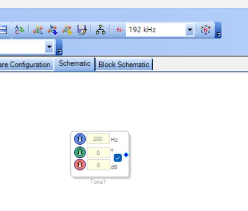
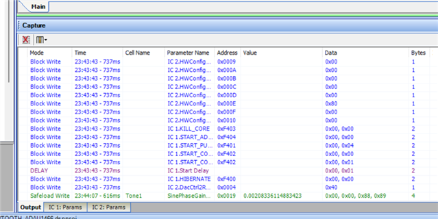
Hello,
This turns out to be quite an interesting problem to figure out. The standard formula of 2*f / Fs happens to be exactly accurate at certain frequencies, for example when the number of samples in one period is a power of 2. Hours of experimentation led to this spreadsheet formula which matches the SigmaStudio calculation for Sigma300/350 DSPs at the 192K sample rate:
Parameter = ROUND((2*f / Fs)*16777216,0) / 16777216
For example, at 200 Hz,
2*f / Fs = .00208333333..., x 16777216 = 34952.533
Round this to the nearest integer = 34953
Divide by 16777216 = 0.00208336114883423
It looks like what's happening is that the parameter drives how fast the DSP goes through an internal sine lookup table to generate the block's output. If the desired frequency doesn't fit nicely into the LUT's divisions, the SigmaStudio compiler fudges the frequency a tiny bit (we're talking parts per million here). This prevents jumps in the sine output which would occur if some LUT rows were skipped. Edit: This turns out to be incorrect -- see my following post. All this of course is just a guess on my part; folks a lot smarter than me designed this thing. This exercise serves to remind us of the discrete nature of digital signal processing.
If you're curious about the stuff I tried to make this work, here's the spreadsheet:
6330.Parameter-calc.zip
Best regards,
Bob
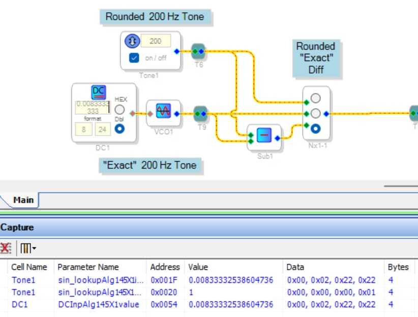
Well, let's go down this rabbit hole a bit deeper... What happens when we actually run the DSP with two oscillators -- a fixed oscillator set for 200 Hz, and a VCO fed by a DC source of 0.002083333.... ?
Of course, the packaged oscillator's parameter goes to its usual value of 0.0020833611... (not shown in the Capture Window above). What's more interesting is what the DC Source does, which depends on how many 3's you place in its window. With three trailing 3's, it sends the first value shown above to the DSP, which is too low. Add one more 3 and it skips over the exact desired value of 0.00208333333 to the bottom value shown above -- which is exactly the same value as that of the fixed oscillator! Notice that the two values in byte form differ by one LSB. Thus, the difference between the ideal 2f / Fs parameter and what SigmaStudio shows in the Capture Window is not from any rounding by the design of the oscillator, as I had originally guessed. It's really caused by the inherent resolution of the 4-byte word in the chip's Parameter storage. BTW, the two oscillators do exhibit a slight frequency difference with only three trailing 3's in the DC source to the VCO. This can be shown by listening to their sum or difference.
There are two morals in this story. The first is, never assume anything. Reverse engineering can miss important details. I had thought of doing this experiment earlier but just didn't bother. The other is -- for best frequency accuracy, run the oscillator at 48K which quadruples its parameter value and thus its resolution. Below is what things look like down at 48K:
If you need to run everything at 192K, you may be able to run your oscillator at 48K via multirate processing, which I believe these high-end DSPs support (but I have not tried).
Best regards,
Bob

Please log in to reply.