Why does the dynamic range of digital input become smaller after DSP?
We use the ADAU1452, the digital audio input passes through the ADAU1452 and then the digital output, the dynamic range is 86dB. But the digital audio input skip the ADAU1452 to digital output, the dynamic range is 139dB.Does the DSP need to do any configuration for this audio dynamic range indicator?
Audio Signal Processors
adau1452
Audio Products
software
Sigma Studio v4.6
SigmaDSP Audio Processors
Show More
Hello Mia,
Mia said:
the digital audio input passes through the ADAU1452 and then the digital output, the dynamic range is 86dB
I'm not sure that how you would say it's 86dB.
When the audio data is in the serial ports it's a 24-bit audio. which is represented in 1.23 format.
Those 24 bits will give you the dynamic range of 144dB. However, the core is 32-bits. So, inside the core you will have a headroom. Inside the core the audio format is 8.24. This is why you can set it for up to +42dB. Please look at the below picture from the datasheet. when the audio goes out to the serial output ports, extra bits (which gave a headroom inside the core) are truncated, and the audio will again become 1.23 which is a 24-bit audio.
I didn't understand how you had come up with that 86dB and 139dB dynamic range? could you explain it in a little detailed way?
Regards,
Harish
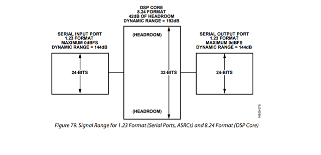
Hello Mia,
Harrish gave you a great description of what happens in the DSP core. If you just pass in the data and then send it right back out there will be zero change. However, if the serial port settings are not correct you can run into problems where the bits are shifted.
The serial port settings on the sending device must be the same as the receiving device. Let me give a few details.
From the viewpoint of the DSP, if the data coming out of the serial output port going to a DAC is shifted to the right. Then the sign bit is lost and there will be a heavily distorted signal. If the data is shifted left then you will clip 6dB early and there will be a lot of distortion when you reach -6dBFS or greater for a 1.23 signal.
From the viewpoint of the DSP, if the data coming into the serial input port coming from an ADC is shifted left, then the audio is 6dB louder and you clip early. If it is shifted right then again, you lose the sign bit. Lots of distortion. Both of these will effect the dynamic range.
So my guess based on almost no information from you is that you may have issues with the serial port settings between devices? Looking at the LRCLK , BCLK and SDATA on an oscilloscope to see what the data format actually is can be helpful.
Dave T
Hi Dave,
I have some questions about the data shift.
You said from the viewpoint of the DSP, if the data coming out of the serial output port going to a DAC is shifted to the left , then it will clip 6dB early.
Assume the serial output port is set to LF and the DAC is set to I2S format, so the data is shifted to the left.
The first bit output from the serial port is sign bit, the DAC miss the sign bit too.
I just can't understand why it will be 6dB clip.
The same question comes when datas input from ADC and data is shifed left.
Thanks.
Foster
Hi, Dave,
Thanks. we have fixed the issue.
Hello Foster,
I could not respond to your PM because your account is setup to not allow messages from someone who is not your friend. So send me a friend request.
Here is my answer to your question that is not visible here in this thread:
Hello Foster.
I will try to put together a document showing what happens when the settings are misconfigured.
The shifting you are asking about is not done in a core or other processor. It is a shift register so it is not an arithmetic shift. some of this may depend on how the digital code was implemented when the parts were designed. Usually the data is shifted into a shift register that starts with the sampling rate clock edge and shifts in all 32 bits of each channel. Then at the end of the frame it does a parallel load from the shift register into a set of flops or other holding register/memory. which 32 bits it picks up depends on the settings. Remember it could be 24 bit data or 16 bit data and it can be LJ or not LJ (I2S mode) . So the register settings will setup this transfer to point into this 32 bit shift register. If it is set to pick up 24 bits then it picks up the 24 bits either from the first 24 bits that were shifted in (LJ) or one bit over from it (I2S mode). If the sending device and the receiving device are not set the same then the sign bit can be lost or it can be shifted over so the sign bit is not seen as a sign bit. In this case the data is not really shifted over, it was just picked up improperly but if you look at it on a scope or in SigmaStudio the data appears to be shifted over.
There are four combinations of what could happen. The sending device puts the data into the 32 bit slot LJ or I2S mode. The receiving device picks up the data either LJ or I2S mode. Two of the four combinations will yield good data. I think I can detail this in a table:...
Sending Device
Receiving Device
Results
LJ
LJ
Good
LJ
I2S
Error Case 1
I2S
LJ
Error Case 2
I2S
I2S
Good
Error Case 1:
MSB is not picked up. LSB is probably always zero
Since most of the time the MSB-1 will be a 1 when negative, the result will be -6dB loss of level but when a high positive number is there it will be perceived as a negative so a huge discontinuity in the decoding of the signal. It will suddenly change from positive to negative and then back. I will try to capture this waveform for you when I get a chance.
Error Case 2:
MSB is most likely always zero. This depends on what the sending device does after the 24 bits are transmitted. Does it drive the unused bits to zero or does it tri-state? Most likely it will be zero.
The LSB is never picked up so it is truncated.
This means the number is always positive. It will be a chopped up distorted waveform because at the zero crossing all the upper bits will change to a "1" when it goes from positive to negative. Look up 2's compliment data and you will see what is happening. then get rid of the sign bit and make it positive then it will jump from zero to a high positive number!
Dave T
Please log in to reply.