Adau generating random noise after some time
Hi,
We are using the adau1701 as a DSP in an active speaker which is already in production.
Now we are having customer complaints about a loud noise generated by the speakers after some time.
The first time they have the noise problem is rarely at start-up but most of the time after some time active playing. (some times ours, but also some times after weeks)
Once the speaker has this problem, it keeps having it for multiple start-ups.
Some faulty modules are send over and we discovered the DSP generates the noise. But it is really inconsistent.
A faulty module can be triggered into the noise state by disrupting the crystal or most of the times it starts doing it by itself. Very strange but after some start-ups, the faulty modules just stop producing the noise, and work as if nothing is wrong, we can not get them to the noise state anymore. We have also tried to trigger the noise problem on new modules from our stock, but without succes, so we don't know the initial trigger to get them to this noisy state.
I have found related issues where to much instructions could trigger a similar noise issue. I am using 1016 out of 1024 instructions and data ram 1962 our of 2048. Is this a problem?
I can't understand why this would trigger a reoccuring problem? if this was the problem I would think that it dissapears after a new start-up?
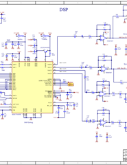
(schematic and dsp project are added)
Any advice for further debugging would be much appreciated
Thanks
PX2xx.dspprojPDF
Audio Signal Processors
Audio Products
software
SigmaDSP Audio Processors
adau1701
Hello SimonPvs,
I think we might have to take this offline to get more details. I sent you friend request. Respond then you can send a PM.
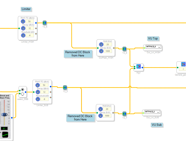
I took a quick look at your project. I think it could very well be an issue with instruction usage. I noticed you have several DC blocks well into your signal flow. I feel that having the DC blocks right at the inputs, where you have them, is good but then unless there is some other way you might get DC into the signal you will not need more later in the signal flow. That would be an easy way to reduce instructions.
I do suspect the PLL may be involved here. If it does not lock properly then it can run the core at an unusual frequency.
You have done some good work trying to replicate it on bad units. These are the kind of problems where small clues will be important so I think it would be best to talk at some point. I see you are in Europe, I am on the east coast and I am often up early so we should be able to talk during your afternoon in the next few days.
Meanwhile, I will read your descriptions more closely and look at your schematics and come up with some plans.
It certainly would be nice if the issue would cooperate and be easily able to be replicated!!
More to come...
Dave T
Hello Simon,
A couple of things to try.
First, regarding possible usage of instructions being too high.
Remove these two DC blocks and the usage drops from 1016 to 1002. This should be fine and not run into issues when doing safeload writes.
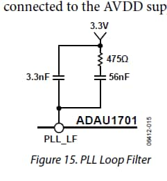
Next is the possible PLL issues. The loop filter is a possible source of flaky locking problems.
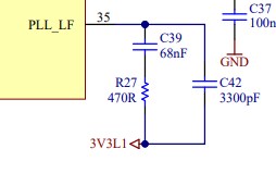
You did not use the values stated in the datasheet.
Datasheet:
Your Schematic:
The 475 ohms is just outside a 1% tolerance but really should not be enough to be significant.
However, the 68nf should really be changed to a 56nf.
Plus, another thing we do not mention in the datasheet is that it is best if these caps are decent quality, NP0/C0G are best to use for their temperature stability and good HF characteristics.
You are tying the filter to the correct power rail but I would like to see how you did it in the PCB layout? The filter components should be on the same side of the PCB as the DSP and you should not run through any vias to get to pin 34.
This gives you a few things to try. I will set something up for Thursday.
Thanks,
Dave T
Hi Dave,
We have done some testing but are not able to pinpoint the problem yet.
First of we mounted a 100nF between pin 33 and 34. This did not change anything, the noise problem still occurred. As we only have one module left which produces the noise, we did not try to lift the pins of the adau yet (out of fear of breaking them).
The number of instructions were lowered.
We noted on this module that the crystal did not start. First I thought it did, but it actually started when measuring on the output of the crystal. When measuring on the input, we could see that it did not start. So we replaced the crystal with an oscillator, but unfortunately, the noise was still present. When using the oscillator on this module, the noise does always come back at every boot cycle. (we tried an oscillator on a working module, and it worked properly)
So I don't think we need to suspect the oscillator/crystal anymore?
We are waiting for C0G capacitors to replace the X7R caps currently used in the PLL filter. But I don’t think it will make a difference as we already tried to replace the caps with new ones (X7R)?
Do you have other ideas to further debug this problem? Preferably without lifting pins, but if you think it is our best next move, we will try it.
I have send an email with the Altium project and a pdf with the layout and schematic.
Any further help would be appreciated.
Please log in to reply.