Understanding performance differences between Parametric EQ and 2nd order filter
Hello,
I'm new to using SigmaStudio to program an ADAU1701 that I'm planning to use for as a DSP for my application. As part of my testing I am trying to characterize the response of some of the filter blocks by running some testing, and have come up with some confusing results.
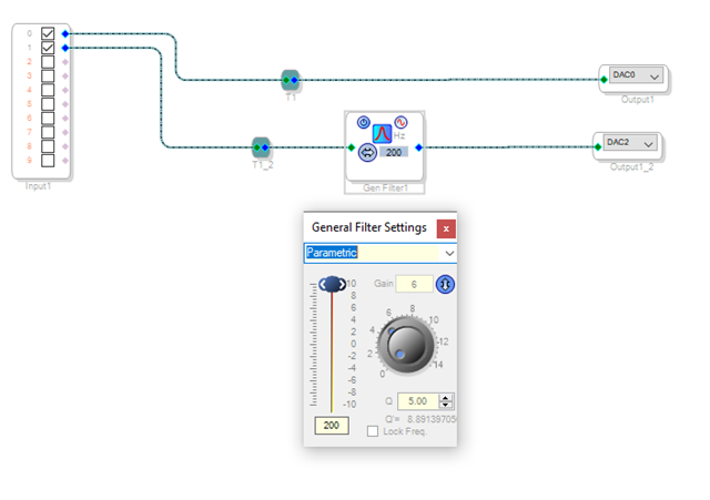
I am generating pure sine tones at various frequencies, and using them as inputs to the adau1701. I then read the adau1701 outputs after my processing blocks and compare the input signal to the output signal. Here's an example of my program with a single General 2nd order filter on one channel.
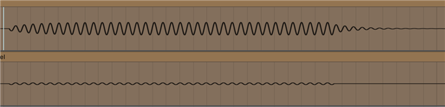
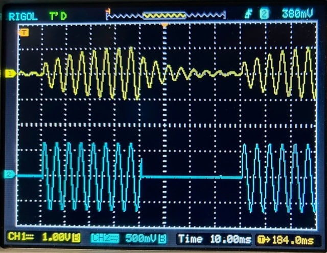
With this setup, I expect to see the unmodified tone on DAC0, and the filtered signal through DAC2, with a 6db gain 200 hz. However, when I run this program I see a very ramp in power, and a very slow signal decay of around ~250ms. (image has DAC2 output on top, DAC0 output on bottom)
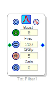
If I replace this filter with a parametric EQ block with a single filter with matching parameters, I also see ringing at the first harmonic. However, if I replace the block with a text-in unlinked filter with the same parameters, suddenly my output is exactly as expected.
My expectation would have been that using a Parametric EQ with a single filter, a general 2nd order filter, and a text-in unlinked filter with the same parameters would perform equivalently, but this doesn't seem to be the case. Could someone help me understand why these are functionally different filters? And why it seems the performance of a PEQ and a General 2nd order filter appear very poor in my testing, while the Text-in 2nd order filter behaves as I would expect? Thank you for any help in understanding this.
Thread Notes
GenevaCooper - Moved from How to Use EngineerZone to SigmaDSP Processors & SigmaStudio Dev. Tool. Post date updated from Thursday, January 18, 2024 5:09 AM UTC to Thursday, January 18, 2024 3:42 PM UTC to reflect the move.
GenevaCooper - Moved from How to Use EngineerZone to SigmaDSP Processors & SigmaStudio Dev. Tool. Post date updated from Thursday, January 18, 2024 3:42 PM UTC to Thursday, January 18, 2024 3:42 PM UTC to reflect the move.
Audio Signal Processors
Audio Products
SigmaDSP Audio Processors
adau1701
Hello EZaro,
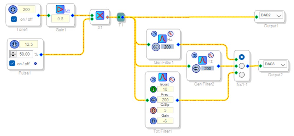
I attempted to duplicate the issue with the project shown below:
The three parametric filters share the same specs: Boost 10, gain -6, Q 5, frequency 200 Hz. Top one is single precision, middle one is double precision, the bottom of course is text-in. By working the switch mux, I found that each gives the exact same response, one of which is shown below:
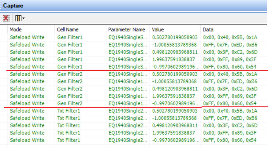
DSPs are essentially multiply-and-add machines. Second-order filters are implemented with two multiply-and-add operations using the present input sample, two delayed input samples, and the past two output samples. Each of these is scaled by a coefficient -- for a total of five coefficients which determine what the filter does. When we compare the sets of coefficients for each of my three filters, we find they're identical. Thus, it's no surprise that the filters behave identically.
Without your project, I cannot reproduce the different results observed with your text-in filter. If you still have the project, try sweeping your input frequency to see if you really have an effective filter! This is because the buildup and decay we see here is quite the normal response of such filters. In effect, the second-order filter is like an oscillator that doesn't quite oscillate. It resonates. The higher the Q, the longer the response "tails." For example, look at this Wikipedia entry on Q. You'll see a graph of the decay at Q = 5, which is similar to the response we're getting here.
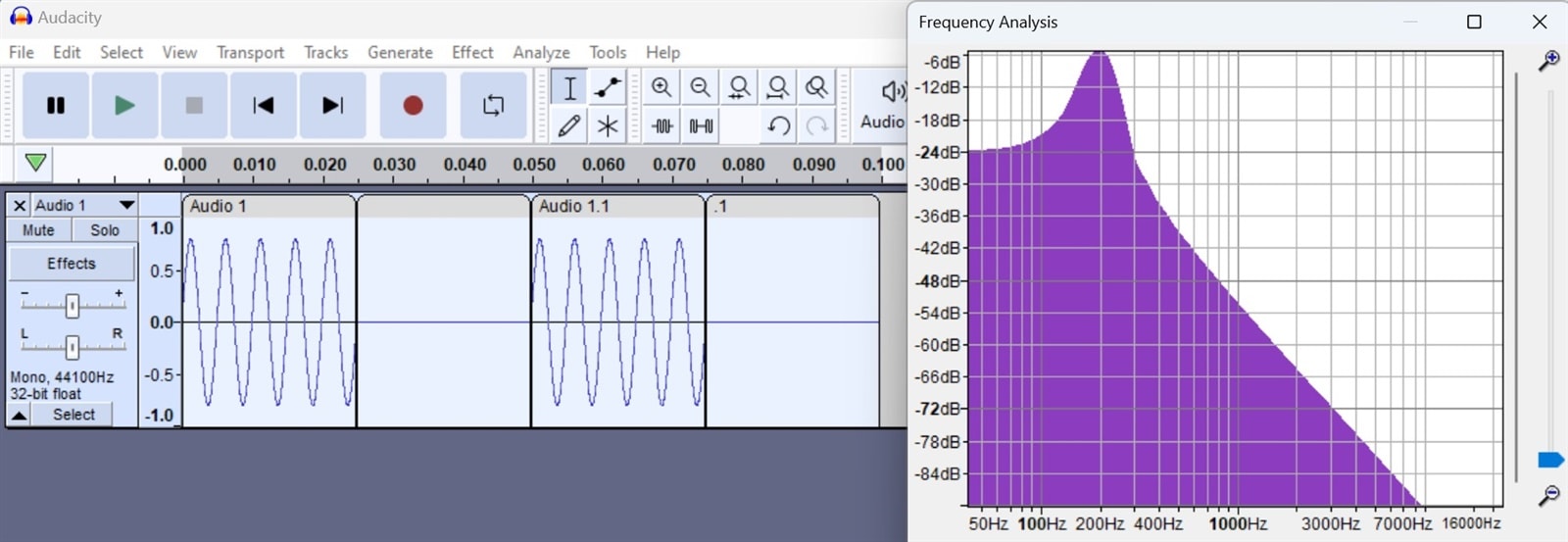
We can also explain this result from a frequency point of view: Although a 200 Hz sine wave contains only 200 Hz, switching it on and off adds frequency components which we can observe from a spectrum plot. Filtering this removes some of these extra frequencies -- which necessarily smooths the switching events. The time domain and the frequency domain are inexorably, mathematically connected -- if this weren't the case, perceptive audio encoding (like MP3) wouldn't work.
Best regards,
Bob
Hi Bob,
Thank you very much for this informative answer. It has been incredibly helpful in understanding my project more.
Based on your response, I think I must have either mistyped a Q value during my test, or simply failed to reprogram the ADAU1701 appropriately between filter tests, so that I was not running symmetrical filters. I have gone back and rerun my tests with a few changes
1. I noticed in my input signal that the cutoff for a given sine tone was not necessarily at the 0 point in its phase, this caused a square wave like transition that seemed to be adding other frequency components. I believe this is what you're referring to in your response as well.
2. Confirm that my setting were actually taking effect between filter changes, and triple checking that they were the same.
In my new test. I do observe that all these filters behave identically. Thanks again for the resources and in-depth answer!
Please log in to reply.