Questions about implementing I2C for adau1701
Good afternoon!
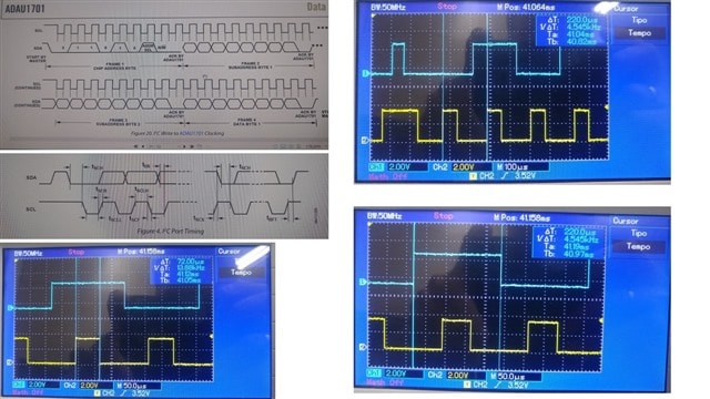
I am having problems using the ADAU1701. I'm trying to communicate (record it for the first time) with an STM32 via I2C, however, I didn't find a library (of stm32) that can help me with this communication, I only found an example of how to use the files, but without the process of sending the I2C. I made some commands that are sending the file information, I tried to use the I2C times that are on pages 9 and 24 of the ADAU datasheet, but I can't reach these times, can anyone help me?
Audio Signal Processors
Audio Products
hardware
adau i2c
SigmaDSP Audio Processors
adau1701
Show More
Hello Phil83,
Have you read this Wiki help page?
Interfacing SigmaDSP Processors with a Microcontroller [Analog Devices Wiki]
Phil83 said:
but I can't reach these times,
What do you mean here? What about the "time" can you not "reach"? The clock speed for I2C is a rather wide range.
Have you captured the communication on an oscilloscope? If you have not then I suggest you do that and see what the controller is actually sending out. This will provide clues as to what is going wrong.
Attach some screenshots of the scope waveforms.
You may want to learn to walk first rather than run. You can program the DSP using SigmaStudio or having it selfboot using the EEPROM. Then just try to communicate with the DSP and change one parameter like a volume control that is really easy to do. Once you can get that to work then you know you are addressing the DSP correctly and then it is a matter of figuring out how to load in a program, the registers and the parameter RAM and get it to run.
You also could just try to read from one register that has non-zero contents by default. Then try to write to one register and read it back.
Dave T
Good afternoon!
Dave, I did look at the wiki and managed to make some corrections to my code based on it. Regarding “I can't reach these times” I'm referring to that my I2C sending speed is much lower than the 400kHz mentioned in the datasheet. I can reach 4.5kHz through my sending code without having problems with different time intervals on my SCL line. I have already programmed my ADAU1701 a little and loaded the programs into its E2PROM, but I was asked to work now on initializing it using a microcontroller, and that is why I am now working on this sending system. I would like to know if it is possible to work with the ADAU1701 using a frequency like the one I mentioned (frequency of 4.5kHz) or do I need to follow the information contained in the datasheet such as times between transitions of both SCL and SDA (the information I refer to in the datasheet I'm posting here).
If my text is a little strange, I apologize, I'm using Google Translate.
Thanks for the help Dave!
Hello Phil83,
Thanks for the clarifications. It would be pushing the part to the edge if you tried to run it at 400kHz clock rate. This is the fastest we guarantee but you absolutely do NOT have to run the clock at that speed. 4.5kHz is a little slow and I am not sure what the I2C spec says for the slowest speed allowed. I think you are still fine. The clock edges will be important and they look fine on your scope captures.
Quick question. When you were self-booting using the EEPROM, did you then use the microcontroller to control objects in the DSP like volume controls and mutes etc.? If you were then your routines were able to properly communicate with the DSP and so now we need to start looking at what and how you are trying to load the program and start up the DSP.
The C-code included in the system Files output should do things in proper sequence. This part is a little simpler than our other SigmaDSPs because the PLL is setup with pins. You do have to apply the master clock and wait for the PLL to lock before trying to program the part and write to registers. Read the Initialization section of the datasheet again for some possible clues as to what is going wrong.
In that section it does state the power up time in a table. Remember that this is after the PLL is given time to lock. Also, note that this table was done using a 400kHz I2C clock. You will be taking a LOT longer to boot up the part at 4.5kHz.
I am guessing costs are trying to be saved by eliminating the EEPROM? Because that is a clean easy and quick way to boot up the part.
Dave T
Please log in to reply.