ADAU1452 simple Sigma Studio Splitter
Hi Dave
Thanks for any help. Chris said to ping you on this.
I am new to sigma studio (ADAU1452) and try to get something super simple working.
I have a single I2S input at 48KHz, 24 bit data, 32 time periods, MCLK is an input going to pin 21 (XTALIN/MCLK) along with BCLK. LRCLK, and DATA.
I simply want to output four copies of this on the four I2S outputs.
I have tried multiple things and followed what I thought was a simple input and output, compile and download but I have seen different things on all 4 ports. Best I have been able to get is after playing with the GUI, to get serial output 1 to reflect serial input 1 however the sample rate was 1/4.
Any chance you could just create a simple project with one in and 4 out and let me give it a whirl. It would take the least amount of your time and probably teach me a lot as I would be able to go thorough it.
Best
Rob
Audio Signal Processors
adau1452
Audio Products
software
ver 4.7 build 0 Rev 1831
SigmaDSP Audio Processors
Show More
Hello Rob,
I doubt that you set the PLL source register as 'Direct from MCLK pin', but you must choose "PLL clock' in that register. That register is not quite correctly named, it's not source to the PLL but the source to the core. If your MCLK is 12.288MHz and you choose 'direct from MCLK pin' then you are running the core about 24 times lower than its nominal clock speed. Its nominal clock speed is 294.912MHz. Below is where you have to set PLL.
Is your MCLK and serial clocks from the same clock domain? If your MCLK and serial clocks are from some different devices, then you should use the ASRC, or you should set the start pulse rate to be the incoming serial port rate. By doing this, you can simply have the core start the frame processing after a new sample has arrived.
The below project is set by assuming your clock is divided from the same domain. I assume you are using serial input port 0 and used that port to receive the signals. Change the same setting if you are using any other port.
Adau 1452 spliter.dspproj
Kindly do reply if anything is required.
Regards,
Harish
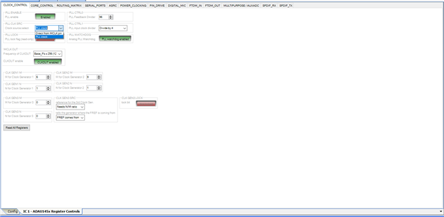
Hello Rob,
I will also chime in along with Harish.
In reading your post a little more carefully. I think you want to take an incoming clock and create four outputs of it on other clock pins correct?
This is not exactly possible with this part. I wish it was!!
By using an MCLK source that I assume is what the LRCLK and BCLK source is using as well? Therefore it is divided down from MCLK and is in sync.
By feeing this clock into the MCLKIN pin you will be synchronizing the parts to run at exactly the same rate.
Internal to the DSP the output of the PLL will be divided down to create the different BCLK and LRCLK rates. since they are divided down from the same clock they will not drift apart and they will be exactly the same frequency. However, the clock edges will NOT be aligned and cannot be made to be aligned. If there was a way to zero the counters that divide down the clock during initialization then they would be the same and not drift but this is not possible with this part. I have tried to work around this.
In addition, when you select which clock to slave a port from, this clock is NOT available for other serial ports to output. The other ports can slave from it but not output the clock from it. The best solution is to use an external clock buffer/driver chip.
By the way, the clock busses for slaving, clock inputs 0-3 are not the same as the clock outputs0-3. There is no bridge internally between the serial input clock domains and the serial output clock domains with the exception of the internal rates of course. But if you want to synchronize a serial input and output ports to an external clock source, then you need to run the clocks to both sets of pins. As an example, if you run a clock to serial input port zero and set the serial input port to slave from clock pins 0. Then you set the serial output ports to slave from clock 0 domain you will get nothing out of the serial output port because it is looking at the serial OUTPUT port clock pins, not the serial INPUT port clock pins. Again, I wish there was a bridge between the input and output ports but here is not. It would have been a timing issue anyway. So you have to externally run the clocks to both sets of pins.
Dave T
Harish,
Awesome, thanks very much.
Yes the clocks are all from a single source (same domain) coming in to the I2S input port 1 and to MCLK.
I think I am inferring from what you are saying is that the PLL is locking to BCLK?
Is the MCLK input even used in this design?
The input port IN_0
is 0/1 the left / right inputs from the I2S in? I am guessing that is documented somewhere obvious but I never saw it.
Best
Rob
Hi Dave,
I want to take the I2S input 1 and put it on the 4 output I2S channels.
Thanks for the tips on the PLL ect..
This part looks super cool but I am blown away that anyone could just jump into this without some help.
The tutorials are neat but (to me) assume you have an understanding of what you are doing. Some videos of the simplest things to get you started would go a long way.
Thank you very very much for responding.
Best,
Rob
Hello Rob,
rbasil64 said:
I want to take the I2S input 1 and put it on the 4 output I2S channels.
The data can easily be routed out of the four serial outputs but the clocks you cannot. They must be connected externally or you use the internal clocks. The possible solutions will depend on what is important to your application.
1) You can do as Harish suggested which is to use the ASRC for the input to convert the sampling rate to the internal rate then set the serial output ports all to be masters then you can drive the rest of the system that way.
2) Which is similar. Since you are using the same master clock as the serial input source is using, you are locked together. So just use the internal clocks to drive the serial output ports and they will be locked but the edges will not be exactly aligned but that might not matter for your application.
I will send you a friend request. I have been working on your last comment and will have some news before too long.
Dave T
I think what Harish provided meets exactly what I needed. I provide the MCLK, BCLK, LRCLK and data and get a locked (x4) output of BCLK, LRCLK and data. Exact alignment is not important.
At the moment I think that is all I need.
Thanks again for all your help.
Best
Rob
Please log in to reply.