ADAU1787 I2S output signal
Hi ADI's
I am testing the I2S output of ADAU1787.
Referring to the link below, I confirmed that I2S output is possible from the EV-kit.
https://ez.analog.com/dsp/sigmadsp/f/q-a/570003/adau1787-i2s-output?
However, even if I turn off the music on the PC connected for testing and even unplug the AUX cable, I can see the signal coming out of the SDATA Out pin.(Same for both channels 0 and 1)
Currently my test configuration is as follows:
PC(audio) - Aux - ADAU1787 EV-kit(ADC) - FastDSP output (I2S)
ADAU1787_ADC_to_SPT_192kHz.dspproj in the link below
Even when testing using Schematic, the same symptoms appear.
https://ez.analog.com/dsp/sigmadsp/f/q-a/569420/adau1787-evb-i2s-in-out-non-reasonable
Is this how it works?
I think that if there is no input audio signal, there should be no signal at the I2S output.
My Customer is unable to proceed due to lack of confirmation of I2S output.
Please confirm.
Thank you
Audio Products
hardware
ADAU1787
Integrated/Special Purpose A/D Converters
ADAU1787 evaluation board
Audio CODECs
Show More
Hello Andrew,
The post you referred to most likely has the answer to their issue.
Have they enabled the HPF to remove any DC offsets?
Have they inserted a mute in the audio path to mute the audio in the core?
They could at least try to mute the ADC to see if the DC offset goes away.
Please have them take a screenshot so we can see what it looks like.
This post is a tutorial about how the screenshots should look.
(+) How to Take Meaningful Screenshots of I2S Audio Signals - Q&A - Audio - EngineerZone (analog.com)
I also have seen the ASRC produce a very small DC offset. It is negative then it will be a lot of "ones" so it looks like data but there really is not any significant signal there. Instead of going to zero it goes to a -1 in integer format which is a very small negative offset.
Dave T
Hello Dave T
Thanks a lot for your help.
I have checked and applied all the advice you gave.
However, even though I removed the EV-kit's ADC input (AUX cable), I still see some output on the scope.
Attach the schematic file currently being tested.
Please check if the configuration is correct
FDSP In_Out Test.dspproj
Thank you
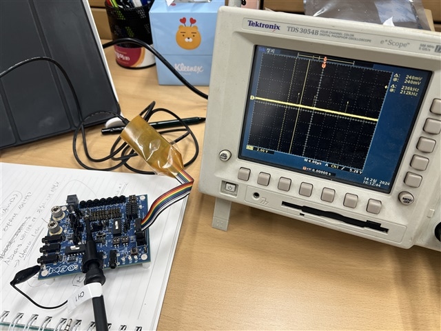
Hello Andrew,
First you MUST trigger your scope to the sample rate clock (LRCLK). All this is telling you right now is that there are some "1"'s in the stream. It could be a "1" in the LSB or a "1" in the MSB (sign bit) which is a huge difference. Looking at it with the LRCLK as a reference and also preferably the bit clock then you can see what bits there are and if the data is changing etc. I think I mentioned all this in my post about !2S but I did write that a long time ago.
Also, you cannot tell which channel the data is on without the LRCLK reference. You are sending four channels to the serial ports.
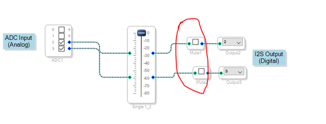
I also suggest you add some mutes in your program. This will allow you to confirm which channel is appearing where in the system. Plus, this is a digital mute so the output will be zeros.
Dave T
Hello Dave T.
Many thanks for your support
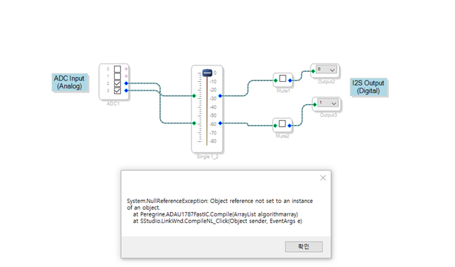
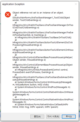
1. I have configured mute in Schematic, but when I click "Link Compile Download", the following message appears and no sound is output.
So I'm testing without mute.
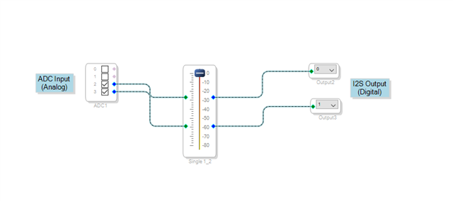
2. I deleted all test blocks and tested again, leaving only Analog input/Digital output.
7532.FDSP In_Out Test.dspproj
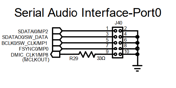
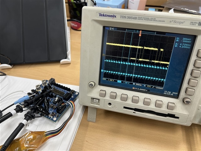
The output waveform was checked at pins 3 and 5 of J40.
2-1 The AUX cable is connected to the PC. (Playing audio)
2-2 The AUX cable has been disconnected from the EV-kit.
It looks like some signal is continuously being output.
I try "Link compile Download" again just in case, but the situation is the same.
3. During testing, there were additional things that were confirmed.
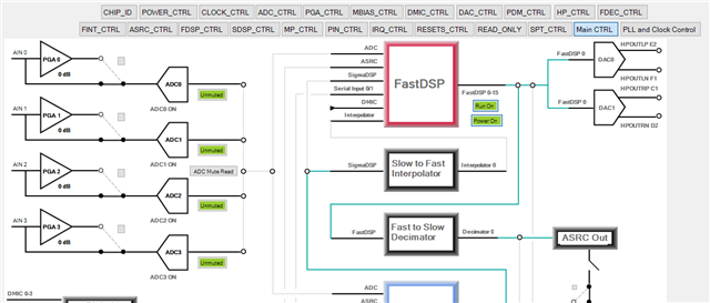
In the Main_CTRL tab of Register Control
If ADC2/ADC3 are muted, the output waveform will not be detected.
but, If turn off the power of ADC2/ADC3, I can still observe some output waveform.
What else should I check?
Thank you

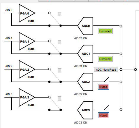
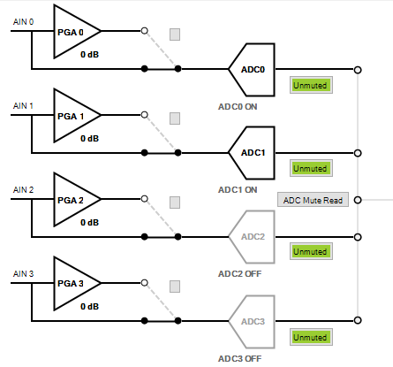
Hello Andrew,
You are still not using the correct signals for the scope.
It is pins 3 and 7. Fsync is another variation of saying sample rate. It means Frame Sync. Earlier I had said LRCLK which means Left/Right Clock which is the sample rate clock. If you have an I2S signal it is only two channels so Left/Right makes sense. If you have a multi-channel TDM format then Frame Sync makes more sense but they both are the same thing. The sample rate clock.
Then I see in the photos that you are triggering to the data. You have to trigger to the sample rate clock.
Did you verify that you are actually seeing the ADC channels 2&3 on that serial output port? When I looked at your project the other day it did seem to be correct but I always double check myself by adding a signal and looking to see if it is there and then remove it or mute it.
The ADC mute is a good thing to do. I know you have the HPF on the ADC so that is good and the mute should mute the DC offset as well from the converter so I do not see an issue with what you did there. I am wondering if the ASRC that is part of the serial port might be the issue here? Usually they do not have much for noise or DC offset so I would be surprised. Once you have your scope properly setup then you can see if the data is changing or if it is the same for both channels? How many bits? It is looking like you have around 8 bits of noise which is a lot.
Regarding the compiler error you ran into. Your project might have been corrupted at some point. This processor does sometimes have issues with SigmaStudio and programming the fast core. I would have to test it here.
See if you can get a little further then let me know what you find and include your latest program like you have been.
Dave T
Hello Dave T
Many thanks for your support
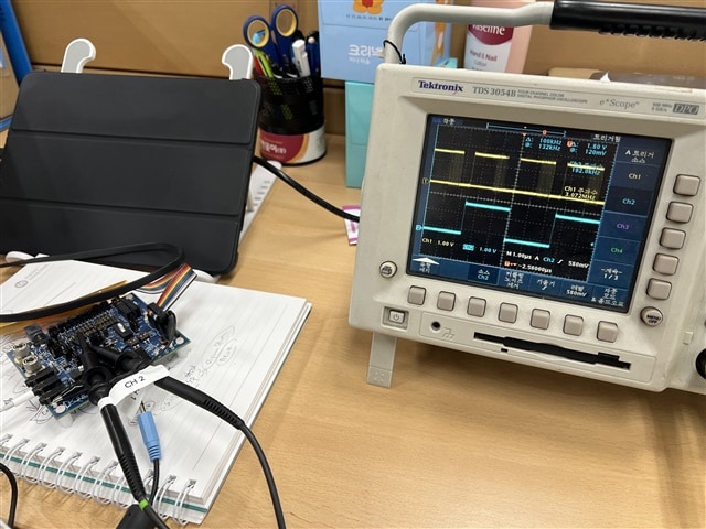
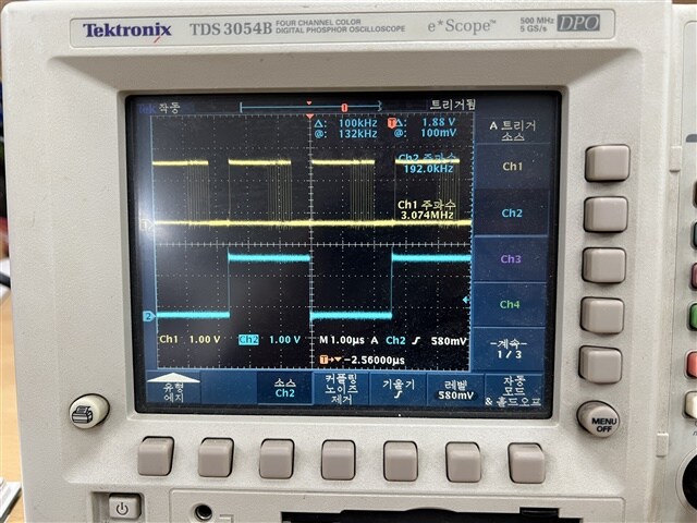
This is the scope waveform taken at Pin 3 and 7.
ADC Input
Without ADC Input(disconnect AUX cable)
There doesn't seem to be any particular difference with or without input.
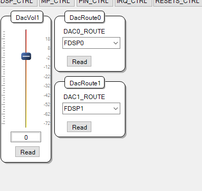
I am testing by setting the DacRoute0/1 regeister in the DAC_CTRL tab of Register Control so that I can hear sound through earphones when there is ADC input (audio).
Going back to the basic question...
If there is no input, what signal is sent to the I2S output (pin 4 of J40)?
Thank you
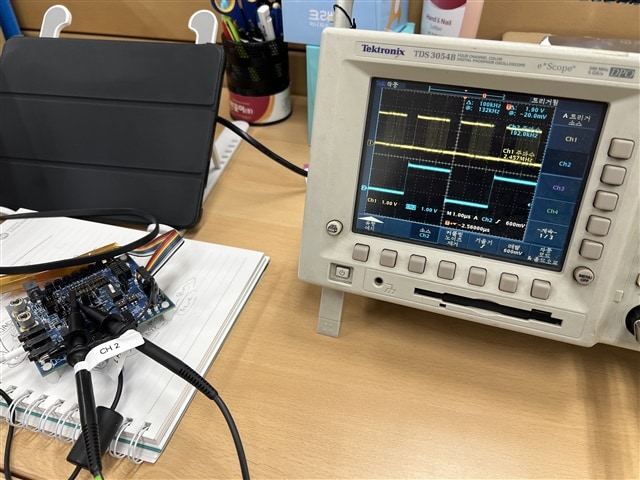
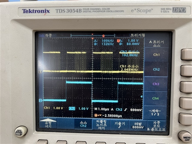
Hi Andrew.Choi ,
I downloaded your provided SigmaStudio project and updated it to include Mute Blocks for each of the ADC channels, and you shouldn't have any issues attempting to Link Compile Download the project to the ADAU1787. (Please see below for the project file)
ADAU1787_ADC_to_SPT0_192kHz_SR.dspproj
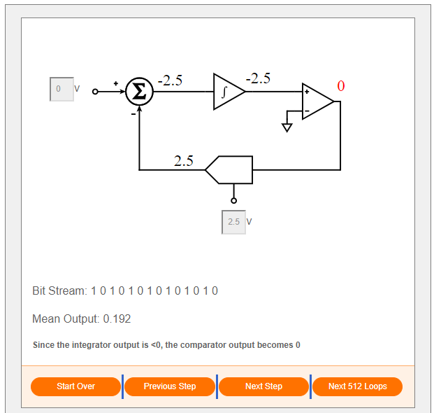
In terms of understanding what to expect for the I2S data, I think this learning module about our Sigma-Delta ADC Tutorial will help understand why there are still non-zeros digital values on the SDATA line. Link
If you were to provide a zero-voltage input to the Sigma-Delta ADC, you will still see a toggle of bits in the output bitstream. This is because the ADC is continuously sampling values that are near zero, but infinitesimally small values still require a good number of bits from your ADC bit-resolution to be represented in the digital domain after sampling.
So, you should expect to see a variety of low digital byte values at the output of the ADC when sampling a near-zero continuous voltage signal. A good rule to determine how many you should expect to see is one bit per 6dB of signal. So, if the ADC has 24-bit resolution, and you are sampling near the noise floor of -120dB, you should still see about 20-bits of resolution when sampling in the output stream of the ADC for a near zero input voltage.
I hope this explanation and the interactive module helps clear up some confusion.
Please let me know if the provided SigmaStudio project also works on your setup and can mute the ADCs. Thanks!
Best,
TBM
Thank you Mr TBM
I will test it with the file you shared.
Thank you
Thank you All
I confirmed that the I2S signal is output normally.
Thank you
Please log in to reply.