TDM4 Unexpected Output
Hi Team ,
We are faced with a strange predicament while using the ADAU1466 Evaluation Board
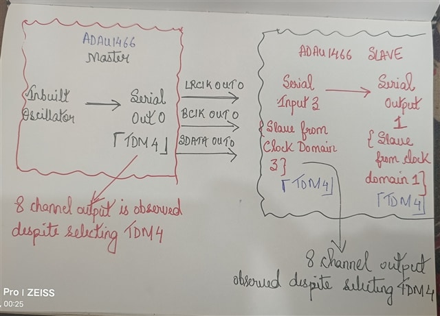
We are using two boards, one is the Clock Master and the other is the clock slave .
I would have loved to share a block diagram but at this moment I do not have one but I will try my best to furnish as much detail as possible to make this post understandable.
First , both the boards operate at 48kHz Sampling frequency.
FLOW IS AS BELOW
Now it is not understood why despite selecting TDM4 , output is observed for all the channels in the Serial Out 0 of the Master Board itself and then the same error propagates to the other board and manifests itself in Serial Input 3 Nd Serial Output 1 of the Slave board
The other common serial port settings for both MASTER and Slave board are as below :
1. Left Justified.
2. 50/50 Duty cycle
3. Both Lrclk and Bclk Negative polarity
4. Tdm 4
5. Fs
6.Tristate unused output channels.
7. Bit depth 24 bits
Can you explain this rather strange behaviour or am I missing something for TDM4 ?
Regards,
Hermione
Edit Notes
Grammar
[edited by: Hermione at 7:02 PM (GMT -4) on 14 Mar 2024]
Audio Signal Processors
Audio Products
hardware
@DaveT
SigmaDSP Audio Processors
adau1466
Show More
Hello Hermione,
Can you supply a project? This may be a simple register setting on a serial port and we could go back and forth for weeks guessing about it.
It is the bit clock rate that determines the number of channels. The registers will say TDM4 and 32 bit wide slots so it will set the bit clock rate accordingly. However, if you feed it a higher rate then it will continue to output data from the large shift register for the serial port.
Send over a project that shows this behavior and let's start there. The one that is the master is the best project to send. This way I can see the clocks that are being produced.
Dave T
Dear Dave ,
I am sending over the project to you .
This code is a little modified so it would be okay to discover the inbuilt oscillator being replaced by Serial Input 0 via ASRC for using SPDIF Input .
The core problem however remains the same , wherein setting TDM4 still brings more than 4 channel output on the Serial Port.
master code 1.dspproj
Regards,
Hermione
Hello Hermione,
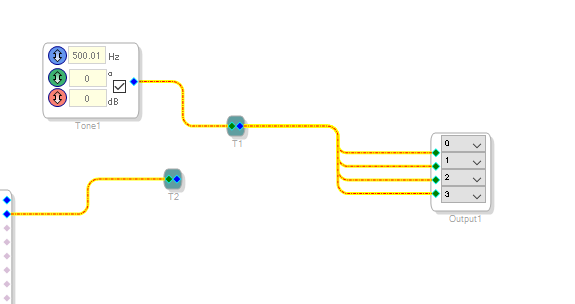
I added an oscillator and I did change the core start pulse to come from the internal fs clock that you setup to be 192kHz for the fs setting. You had it as a slave to serial input port 2 and I have nothing there so the core would not have been running.
Both of these changes have nothing to do with your problem. It is just so I could run it on my ADAU1466 eval board.
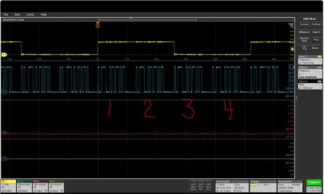
The results is a lovely TDM-4 output out of serial output port 0.
Here is the screenshot of my oscilloscope:
Try this test.
Connect an oscilloscope to the bit clock output of serial output port 0.
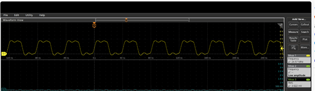
You should see a bit clock of 24.576MHz.
Go into the register settings and change the BCLK output to be a slave to clock domain 0. You should see the clock go away. The purpose of this test it to make sure we know where the clock is coming from and that another device is not driving the serial port bit clock.
If the clock does go away, then turn the clock back on and stretch the scope timebase to look at the waveform more closely. Here is the 24MHz bit clock I have on the eval board:
Look to see if you have a lot of reflections or places where it sags low or bounces high where it might pick up two clock transitions instead of one. Then it will think you are sending it a 49MHz signal. So this might be a signal integrity issue. You then can make changes to the drive strength registers to hopefully fix it or you may have to make some changes in your PCB layout or the value of the damping resistor.
FYI, This is the change I made to the project. Not much...
Dave T
Hi Dave ,
Thank you for the response!
What I had likely missed in the previous post in telling you was the way I had seen 8 channels of data instead of only 4 . It was using the level detectors .
Now I would request you to do just one thing
Let's have two codes one for Master and the other for the Slave
The master code should have a simple oscillator routed to Serial Output Port 0 for TDM 4 at 48kHz Fs.
Now connect physically LRCLKOUT0,BcLKOut0 AND SDATAOUT0 from the Master Board to LRCLKIN3,BCLKIN3 and SDATAIN3 of the slave board . I chose Serial In 3 because the headers are available in the Eval Board and the codec involvement is absent too .
The slave code should have the serial input say Serial Input Port 3 slaved off from Serial Output 0 of the Master . Ofcourse the settings would be slaved off from clock domain 3.
You can safely assume 48kHz Fs in the Slave code too.
Just connect the Level detectors to all the 8 channels of the Serial Input 3 and you will see exactly what I am trying to describe.
And although your observation about both the clocks and data in CRO regarding TDM4 is consistent with mine .
The problem I see here is when I use the Level Detectors on all 8 Channels of the Serial Input 3 set to TDM4 , I would expect to see 4 channels but I see 8 instead
Please try this and let me know your feedback
Regards,
Hermione
Hello Hermione,
I understand your question and it is an expected behavior. If you only have four channels of data in the input buffer and you try to read eight channels of data, the four channels will just repeat on the additional channels. But the data on the streams are undefined and isn't guaranteed to be meaningful.
Regards,
Harish
Hi Harish ,
Thank you for your response .
I am not certain if I understand why this is deemed an expected behaviour .
This does not happen for the I2S case but happens only for TDM4
Another thing worth mentioning is that the Level detectors show that the output in the remaining channels are exactly of the same dB level as expected.
And then there is also an option to tristate unused output channels which means the remaining unused channels should not be driven so in that case why would there be all 8 channels of data instead of 4.
Nevertheless, at the moment what is also very important for me to know is which of the four channels are indeed the correct ones for me is it the first 4 last 4 or is there a way to discern them from the invalid ones because all show correct amplitude levels in the level detectors.
Regards,
Hermione
Please log in to reply.