Need assistance on debugging a possible issue with merging the input channels and causing clipping
Hi,
I'm debugging a strange issue with a crossover based on ADAU1466. I tried various settings in Hardware Configuration but running out of ideas, so appreciate if you can help root cause the issue.
Issue description:
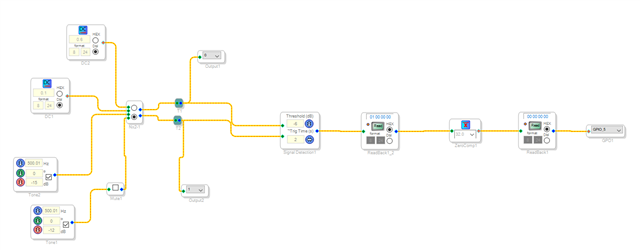
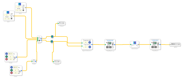
If I run a test 2kHz -3dB sine signal on only one channel and digital silence on the other channel, there is no issues on DSP output. But if I run the same test signal on both L and R input channels, then my clipping detector on DSP output before DACs activates, so I suspect my DSP configuration is unintentionally adding/merging the two input channels somehow.
Setup description:
SigmaStudio ver. 4.6
ADAU1466 DSP, external master clock input to DSP 24.576MHz, digital optical input through the SPDIF receiver, output to 3 24-bit stereo DACs through I2S bus.
DSP configured as a 3-way speaker crossover. Internal sampling rate is set to 96kHz.
After all filters just before the output ports to DACs there is a clipping detector made by a 0dB level comparator that blinks a LED for a two seconds when detect clipping. Detector activates if I increase the signal level so I think it is working correctly.
There is a timer used as a reset generator for the DACs. That is also working as intended.
I've checked each of the DACs analog outputs and frequency response is matching the expected response from filters.
Initially all my filters, gain and delay blocks were defined as a 2-channel blocks. Splitting these into separate blocks for each input channel didn't change anything.
I am attaching a RAR archive with my project and some screenshots from test signals and block diagram of filters as well.
Please let me know if you see anything suspicious.
RAR archive with SigmaStudio project:
drive.google.com/.../view
Test signals screenshot, top: one channel 2kHz -3dB sine, other channel digital 0; bottom: both channels 2kHz -3dB sine
https://drive.google.com/file/d/1Oq2rEPsiGxcxQ_uESaCQxgZxatJS40ny/view?usp=sharing
Screenshot from filters schematic:
drive.google.com/.../view
Thanks,
Plamen
added screenshots
[edited by: ptaskov at 8:53 PM (GMT -4) on 19 Apr 2024]

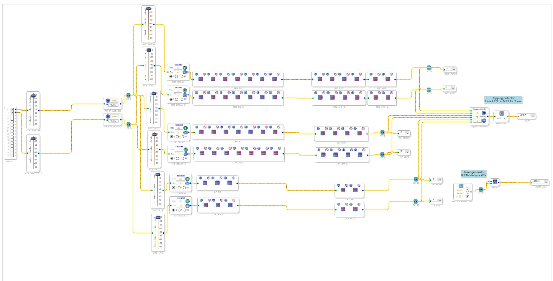
I had a chance to do some experiments:
1. Measured with a spectrum analyzer on each DAC output with a 2kHz -3dB sine test signal on one channel only (other channel digital 0), and then on both channels
In both cases signal level on DACs outputs is the same for L and R outputs, so it seems like there is no higher level when running test signal on both channels. Distortion figures are also similar.
2. Removed all filter blocks, delays and gain blocks, then connected the ASRC's output directly to the serial outputs and clipping detector.
2.1 If I run a 2kHz sine test signal on only one channel, then LED starting to flash for test signal levels higher than -9.5dB
2.2 If I run the 2kHz sine test signal on both channels, then LED flashes for levels higher than -15.5dB (exactly 6dB higher than the one channel case).
Since the spectrum analyzer did not show any different levels or distortion between the one channel and both channels test, then I suspect the clipping detector is not working as I intended.
Regards,
Plamen
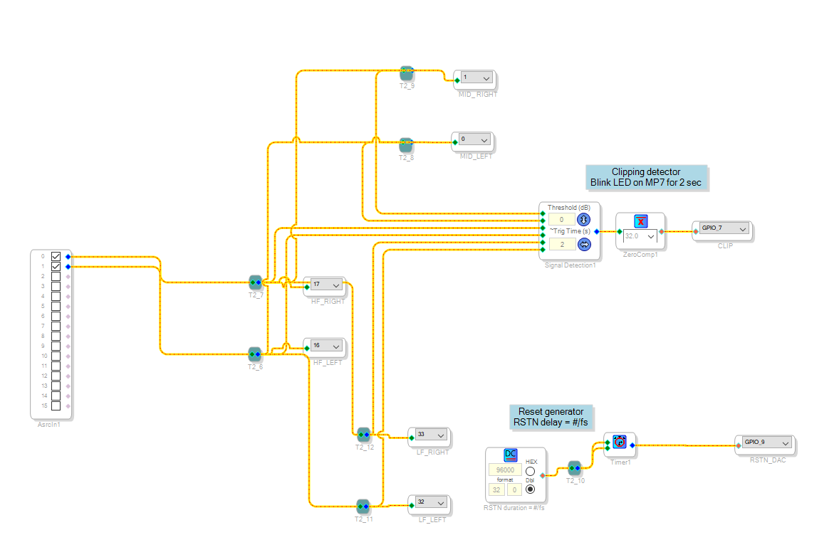
After verified that on DAC analog outputs there is no different level when running test signal on a single input channel or on both input channels, and nonlinear distortion is not increased, I decided to re-work the schematic of the clipping detector and I think that now it's working as expected. Tested it with various input signals.
Here is the schematic of my new clipping detector. If the level of any of the 6 inputs rise above the threshold (0dB), a single pulse with duration 1s is created on GPIO_7.
Regards,
Plamen

Hello Plamen,
I'm glad that you solved that yourself with a new method. Let me see if I have any old project which does this quite efficiently. If I have any, I will post it here.
Reg your original post, I guess when you grow the signal detection block, it will add the inputs and determine the output.
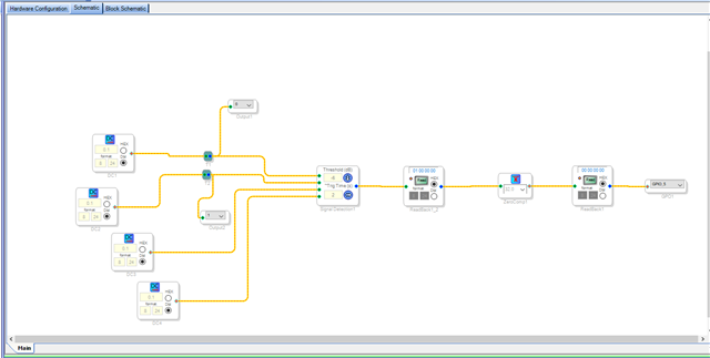
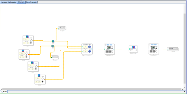
In the below screenshot, I grew the input to four channels and set the threshold as -6dB (0.5 in 8.24 format) and all my inputs added will be 0.4 which is below the threshold (0.5), hence it outputs a '1'.
Now, it's above 0.5, so a valid signal is present hence it outputs '0'.
The same thing might have happened with your test signal.
when you have a signal in one channel and digital zero in another channel, the output of the block will be based on that single active channel. If you have two channels active, then the output will be based on two channels added up. Here I have two correlated sine waves added up, -12dB and -15dB will give you -7.35dB, which is below the threshold (-6dB), hence the output is '1'.
I have two signals which is -10dB and -10dB, now if it adds up it will be -3.98dB, which is above the threshold (-6dB), since it's a valid signal it outputs a '0'.
Regards,
Harish
Hello Harish,
Thank you for providing more details on how the signal detection works and for your help!
Currently my design fits the resourses of DSP but a more optimized solution would be really helpful for me if in future my design grows up or for any other users.
Regards,
Plamen
Please log in to reply.