SSM I2C issue
Hi all...
Good day,
We are working on communication system using AD9361 with xc7z030.
So I'm working with a xc7z030, vivado version 2021.1, and Vitis for Software.
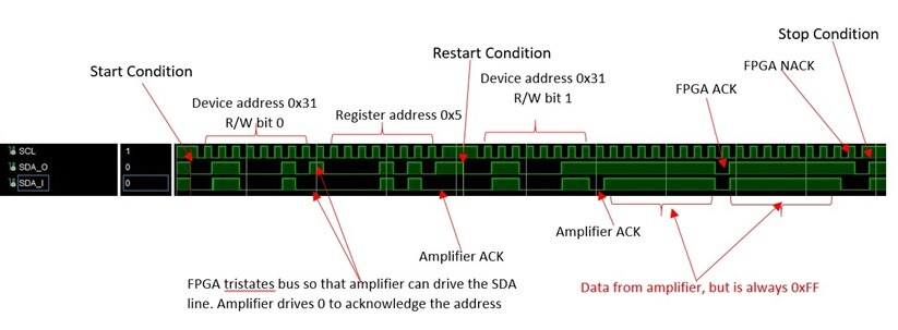
I2C signals read back from audio amplifier(SSM2380) is not giving the expected register values. The read-back register values are always constant 0xFF.
Write is working and during read amplifier is acknowledging address but data is wrong.
a. VIVADO 2021.1 Screenshot for the Writing_0_to_Reg5.
b. VIVADO 2021.1 Screenshot for the Reading_from_Reg5.
Details picture:
Kindly refer the attached picture.
Any help would be very appreciated, since I need to progress on my work.
Thread Notes
Analog404 - Moved from Audio to SigmaDSP Processors & SigmaStudio Dev. Tool. Post date updated from Thursday, May 23, 2024 3:59 AM UTC to Wednesday, May 29, 2024 2:02 PM UTC to reflect the move.
Analog404 - Moved from Audio to SigmaDSP Processors & SigmaStudio Dev. Tool. Post date updated from Wednesday, May 29, 2024 2:02 PM UTC to Wednesday, May 29, 2024 2:02 PM UTC to reflect the move.


Hello Analog404,
First thing I want to mention is that I find it very strange that your data captures have an SDA_O and SDA_I lines on the graph.
There are only two pins, SCL and SDA. So there is only one SDA pin. How can you capture a graph showing two different levels or reading for the same pin?
It is great to know that you are tri-stating and so you can see the "ACK" but it is very strange. There is no way that these are actual captures, it is impossible. A pin cannot be both high and low at the same time and your graphs show that.
Going back to your question about why are you getting all "F" for results yet you are getting ACKs?
I always go back to look for the obvious like is power and ground going to the part? I suspect this is not the issue since you see ACKs.
From what you show in your graphs it looks like you are sending the correct messages and chip address.
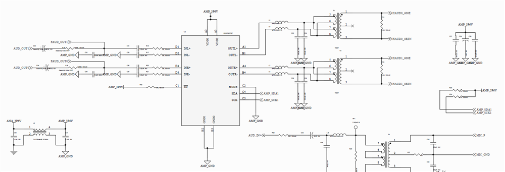
What is the state of the MODE pin in your hardware? Is it grounded?
What is happening with the /SD pin? This can also cause issues.
I am not the engineer assigned to support this part. Those people have been alerted but I can at least get started with these first steps. Let us know about these first two questions I asked.
Thanks,
Dave T
Hi sir,
The Integrated logic analyzer(ILA) scope data we'll try to debug with the designer and get understanding, in the mean time can you just go through the below data and give your insights.,
We have fully integrated RFSOC(AD9361) - Zynq7030 with SSM2380 through ADAU1401A for our Short range communication system.
At times the audio amplifier goes to idle state where its losing its pre-defined configuration which we fed during initialization sequence. Because of this issue, for every instance we are reconfiguring the audio amplifier in a cyclic routine which leads to system performance drop. Can you help in understanding the SSM2380 under which circumstances the device may get reset and how to mitigate this.
Kindly go through the below details for Hardware environment understanding.,
Please Note:
Input Power (Through an LDO): 3.3V instead of 3.6V
Input Audio Power (Through ADAU1401A): 1.8Vpp
Maximum Audio Power Out (Expected): 100mW
Transformer Spec (76367 - Pico Electronics): Pri - 7.5ohm Sec - 600ohm
Kindly go through the below details for Software environment understanding.
Working with a xc7z030, Vivado version 2021.1, and Vitis for Software.
I2C signals read back from audio amplifier(SSM2380) is not giving the expected register values.
I2C - SCL Clock frequency is 100kHz.
The read-back register values are always constant 0xFF.
Write is working and during read amplifier is acknowledging address but data is wrong.
Thanks in Advance...!
Hello Analog404,
You have the I2C pull up resistors going to the 3.6V power (which you did mention is actually 3.3V which is what it should be)
However, you mentioned that the ADAU1401A is running at 1.8v? It cannot operate that low. It is a 3.3V device.
If it were able to operate at 1.8V then you would need an I2C level shifter to go between the two power domains. However, in this case both parts need to be running at 3.3V
This is probably why you are not getting communications.
Dave T

Please log in to reply.