Invalid Addition results with Signal Adder Module
Dear Team,
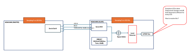
We are using the ADAU1466 and Sigma Studio v4.5 . Our setup consists of two ADAU1466 Evaluation Boards wherein one is Master and the other is Slave. Below is the issue description
I am attaching the Slave code assuming that for Master code you will need to just send TDm4 Clock and data (@192Fs) to this Board from another ADAU1466. The addition result is wrong every time we LCD. Is there any solution to this.
Regards,
ZaynStandaloneSlave.dspproj
Audio Signal Processors
hardware
SigmaDSP Audio Processors
adau1466
Hello Zayn,
Thanks for attaching your project, I will have a look.
There must be a latency between these two processors, so it can't quite add up perfectly. If you try adding two incoming signals, then it will give you correct results.
BTW, you did a right thing by running the core at the serial input rate, I will look at the rest of the settings and get back to you.
Regards,
Harish
Hi Harish !
Please let me know if there is any workaround / solution to this .
Regards,
Zayn
Hi Zayn,
As I mentioned, this is because of the latency between two processors. One (mostly Master) must be programmed and started running before another. The slave indeed starts processing based on the serial input LRCLK (Start pulse set as Serial inputX), but that mustn't be a first LRCLK frame of the Master board. In your case, the time that you have taken between programming the master and then the slave, there may be a few LRCLK cycles from master would have passed (even a few sample periods may create phase shifts).
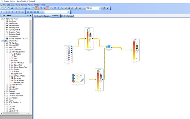
I quickly tried one thing, I put the master board in self-boot mode and set the slave's start pulse setting as serial input (coming from the master board).
As soon as I did link compile download the code to the slave board, it's programmed but the core doesn't start processing because it waits for interrupt (start pulse). Now I turn ON the self-boot switch and hit reset in the master board. So, it starts sending the serial clocks along with data. The slave board also starts processing based on the incoming LRCLK (start pulse). So, both will be processed at the same time (almost). So, you won't miss any samples. please look at the below screenshot.
Updated reply: The internal tone and incoming tone (generated from another DSP) will not be exactly synchronized. Hence the level won't be added up exactly. Please find Dave's detailed reply below.
I'm not sure if I explained it clearly, kindly do reply if you have any questions. Try this at your end and get back with your results.
Regards,
Harish
Dear Harish,
Regarding the programming sequence, I do not see it as a problem. When I program the first board, the LRCLK starts ticking. By the time I program the second board, a few LRCLK pulses will have already been missed, which is logical and expected. In the code I shared, both the Sine Tone Generator and Serial IN 0 rely on the Start Pulse for interrupt, and I have set Serial IN 0 as the Start Pulse. Therefore, both the Sine Tone Generator and Serial IN 0 should miss the same number of LRCLK pulses from the master, which should not interfere with the addition results or create phase shifts as you suggested.
Regarding the self-booting mechanism, I understand it to be equivalent to code loading, albeit with a different procedure. Your suggestion implies that the slave board should be loaded first, followed by the master board. Hence, I believe the loading method should also work. I will test this method and get back to you with the results.
Regards,
Zayn
Hello Zayn,
Zayn said:
In the code I shared, both the Sine Tone Generator and Serial IN 0 rely on the Start Pulse for interrupt, and I have set Serial IN 0 as the Start Pulse. Therefore, both the Sine Tone Generator and Serial IN 0 should miss the same number of LRCLK pulses from the master, which should not interfere with the addition results or create phase shifts as you suggested.
I don't quite understand what you described above, let me address this as much as I can from what I understood from your reply.
The sine tone generator and the serial IN 0 of the slave board are not two different things to miss samples between each other. The sine tone generator is a bunch of code (like every block in SS), entire schematic is converted into bunch of codes which needs an interrupt to start running. If there is no interrupt (if the start pulse is set for something which has no clock on it) then the code will not be executed.
In your case, it gets that interrupt via serial in 0 and as soon as it gets the interrupt, it will take first sample from the tone module and first sample from the serial input (to the salve board, it's the first sample but it's not acc to the master (sine module from master) because you programmed the master board some time ago and it started running, At 48KHz,let's assume 1ms ( 48 samples for each channel) ago, now what you have in the serial input port is appx 49th sample of the master board's tone generator (excluding serial in and shifting delays) and now the adder will add both samples and give you the results (it all happens in one sample period), then the next sample and so on.
If you look closely, you are not adding the first sample of the master board's Tone with the first sample of the slave board Tone, it's like 1mS delayed signal acc to my example, so you won't be getting an expected result, because this won't be a constructive interference and there will be cancellations. So, you will have different results every time when time difference between programming two boards changes every time.
Now, let's see what I explained yesterday, I programmed the master board first and put that in self-boot mode and powered off the board, then I programmed the slave board and set the start pulse as a serial input from the master. Now I connected the jumpers from master to slave, now the slave is programmed but the core isn't running (doesn't execute the code) since it doesn't have anything on the start pulse (serial input) because the master board is powered off.
Now I powered on the master board and turn on the self-boot switch and hit reset button, now the master board transmits the first sample (if you connected the Tone to four outputs using a T, then all four samples in the frame will be the same) of the sine tone along with the BCLK and LRCLK. Now the first frame of the LRCLK carries the four samples (all are same) and the slave board will also start to run as it receives the start pulse from serial input pin.
I know this is not a perfect step by step example I skipped a lot in between, However, this will approximately give you an idea of what I have shown you yesterday.
Regards,
Harish
Thanks, Harish, for your response!
However, we regret to inform you that even after following the procedure suggested by you, the output is far from expected and seems to work only for certain low frequencies (500Hz for example). For higher frequencies the deviation from expected output is very large and also does not seem to have any pattern. Please find our observations below:
Regards
Zayn
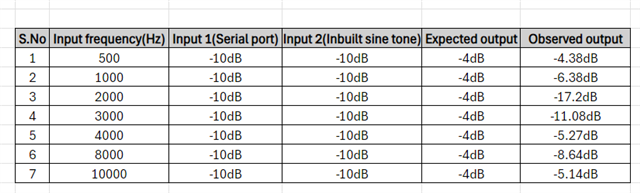
Hello Zayn,
Sorry it took me a while to chime in.
There is no way you will reliably get the two oscillators to be exactly synchronized that are running in two DSPs. There is no way to set the counters that are used to start looking up values in the sine tables to start counting at the same time. You can synchronize the two sample rates and Harish showed you how to do that. This will lock the two so they do not drift in frequency between each other but it does not change the pointers (counters) used to access the sine table. Since you are adding only single samples at a time, the sum will not be double (+6dB) because they are not at the same point in the sine wave. The timing difference will vary with each startup because the program loading and the PLL startup time etc., will be slightly different each start up from cold.
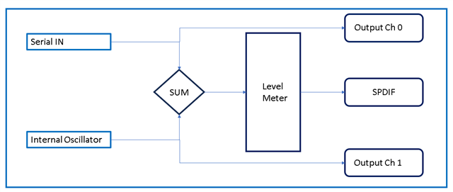
I will propose some experiments to demonstrate this. I drew up some diagrams.
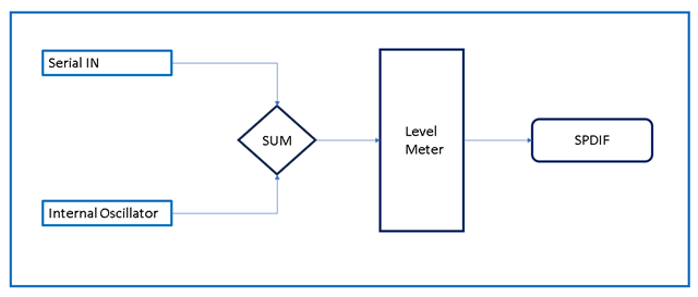
Here is your current experiment:
I propose you make this change as an experiment.
Then use an oscilloscope and look at the two waveforms. With the start pulse set to follow the sampling rate of the serial input port the two sine waves will not drift around relative to each other. However, if you look at the peak or zero crossing they will not be lined up.
The amount they are different in time will change with each startup and this is why the sum is different each time,
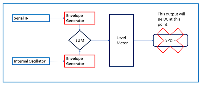
If you simply want to measure and compare the levels then you have integrate them by using some envelope generators. Do it like this:
The only problem is that the SPDIF output will now be a DC value and no longer a resultant sine wave.
I have no idea what your end-goal is for this program so I do not have a suggestions as to what to do about that.
Will the audio always be sine waves in your application? Usually if it is music or some other audio source like voice, they are all not correlated so this problem of the sine wave timing is not an issue.
If it is sine waves then perhaps you could detect the zero crossing, count the number of samples that they are different and then add a delay to one of the sine waves to line them up. Might be able to be cleaver and have the DSP program do this itself... Hmm,... might be possible but tricky. If an MCU is involved then it would be easy.
Dave T
Please log in to reply.