External button to select internal crossovers.
Hello everyone,
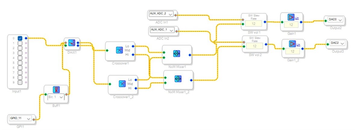
I’m new to SigmaStudio and I’m working on programming the ADAU1401 to use an external button to select internal crossovers. I have successfully set up the blocks for external volume control and crossovers, but I’m unsure how to implement the filter selection block, which is highlighted in red in my block diagram.
In the second figure is what I have already done.
Thank you in advance for your assistance!
Edit Notes
.
[edited by: Paul409 at 4:33 AM (GMT -4) on 15 Aug 2024]
Audio Signal Processors
software
SigmaDSP Audio Processors
Sigma Studio 4.7.0
external crossover select
adau1701
Show More

Hello Paul409,
You have a pretty good grasp of what is going on but there are a few issues to deal with and I also have a question.
First the easy question. I assume the switch is a momentary? Since you want to select between three different settings you would press the switch to move to the next then to the last them come back around to the first with each button press correct?
I will attach two example projects. One for a latching switch and one for a momentary. The momentary one is exactly what you are trying to do.
ADAU1701 GPIO Momentary SW counter to Index Selectable Switch.dspproj
8171.ADAU1701 Index Selectable MUX using GPIO Input.dspproj
One thing you did wrong in your project was to set the zero comparator block to bit1. It should be bit zero. You are sending it a value that is out of range. It is a pointer so it is pointing to memory in the wrong place.
On to other things.
You are using 5V. This is BAD!!!! You will blow up the part.
The IOVDD voltage on this part is 3.3V. You need to use the 3.3V on the board to send to the AUX ADC pots and to the GPIO switch.
You could change the divider resistors for the GPIO to divide the 5V down to 3.3V but for the AUXADC pots you have to use the 3,3V.
for the GPIO you have a 1K pull up to 5V and then 10K to ground. This is a divider. 5 *(10/11) = 4.55V
If the logic voltage was 5V then you are reducing the margin for no good reason. I would use a 10K instead of a 1K and get rid of the 10K to ground. It will be 1/10th the current that the switch has to sink when it switches. But, you could change the divider to divide the 5V by 2/3rds. So if you keep the 10K to ground then a 5.1K instead of the 1K would give you roughly a 2./3 divider if I am doing the math right. 5K would be exactly 2/3. it would be 15K/3=5K. So 10K is 2/3rds and 5.1K is a standard value close to 5K. This will give you just under 3.3V which is on the safe side of 3.3V.
But, for the AUXADC pots you could do something similar. If they are a linear 10K pot then put a 5K1 resistor from the top of the pot to the 5V line. This would limit the travel to 2/3rds of 5V. Use one resistor for each pot so they do not interact with each other.
Dave T
Please log in to reply.