SSB modulation using ADAU1701
Hi to all, I thank in advance whoever can give me an answer.
I am using a demoboard with ADAU1701 (TINYSINE TSA1701) it is a little pretty board and works very well.
Now for my experiments I need to create a signal with a carrier of 40Khz (about) modulated in single side band. As input audio signal I am using a sine signal generator on 1Khz.
After hours spent finally I found this solution, using the Hilber transformate.
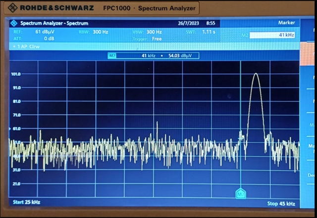
The question is that this project works very well, with my R&S spectrum analyzer I can see both sidebands distant of 2Khz from the center carrier (suppressed).
But.. when I use this project adding these blocks on another more complex the output frequency ot the sidebands is not more the same... the lower seems right, the upper is about 10Khz over..
The input signal is the same.. (1Khz) .. I can't understand why the behavior of this circuit changes like this from a project to another... the samplig frequency is the same, the Sigma Studio is the same, the hardware is the same but the result change..
Thanks a lot in advance,
bst
pierluigi
Audio Signal Processors
hardware
SigmaDSP Audio Processors
ssb
adau1701
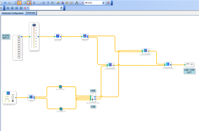
Hello Pierluigi,
It could be that your larger project has exceeded the instruction limit for the ADAU1701 at the 96K sample rate. The -1701 executes at 49.152 MIPS whether running at 48K, 96K, or 192K. At 48K, it can do (49,152,000 / 48000) or 1024 instructions before the next sample comes along. At the 96K sample rate it can do 512 instructions. In all cases we need to subtract some 10 instructions for overhead, so you have just over 500 available for your project.
The last time I looked, the compiler only flags instruction counts above 1024 -- regardless of the project's sample rate. Thus, your larger project could exceed 500 instructions without warning. An oversize project causes unpredictable issues.
Compilers for the newer chips have output windows which report resource usage, but this one doesn't. Read how to check your instruction count in this thread:
https://ez.analog.com/dsp/sigmadsp/f/discussions/101228/determining-resource-use-for-the-adau1701
Your small project shown above uses about 190 instructions. The Hilbert Transform alone takes 100. Nearly ten years ago (gasp! see my avatar) I published a spreadsheet listing instruction counts for popular ADAU1701 blocks:
https://ez.analog.com/dsp/sigmadsp/f/discussions/65644/adau1701-instruction-usage-table
If your larger project is in fact oversize, we may be able to help you shrink it to fit. If not, perhaps we can assist you with troubleshooting it. In either case, it would be helpful to post your project file.
Best regards,
Bob
Hello Bob, thanks first of all for your quick and exhaustive anwser.
Unfortunately my worst nightmare came true. I imagined it was something related to computing power...
I will try to use the new one ADAU1467, the specifications indicate a higher computing power always compatible with sigmastudio, I will have to buy a new demo board, new circuits..
BTW very interesting and well done your xls document, I will keep it as reference.
Have a nice day,
bst rgs,
pierluigi
Hy Bob can I try to use ADAU1467 ? does sigmastudio works in the same way with dsp too?
thanks in advance,
bst
pierluigi
Hello pierluigi,
Yes, SigmaStudio works in the same way with the ADAU1467. There will be some differences due to the different DSP core. The core is 32 bit into and out of the core (the multipliers and accumulators are much wider). The older cores are only 28 bit. So there will be some differences in the fixed point number formats. The AUX ADCs are slightly different. The way ReadBacks are done is slightly different. There are no built in converters so you have to setup the serial ports to communicate with an external codec. I do cover most if not all of this in my YouTube channel. If you have not found it yet I suggest you look it up. Channel Welcome Video!
The ADAU1467 is a huge leap forward in processing power from the ADAU1701. The 1701 is an awesome part but it is a little limited. Bob has managed to do some amazing things with the 1701. You would be wise to follow him and look up some of his older posts. There is a reason he is designated a Super User!
Dave T
So is the answer to use the ADAU1467? I also wish to build a SSB modulator and demodulator. Any carrier freq fine. Voce band 300-3600 Hz. Assume the internal Hilbert is the block to use.? Please advise. AeroS
Questions:
1. What ADAUx part can handle the library Hilbert?
2. Old posts from 10+ yrs ago suggested the use of a quadrature oscillator. (multiply incoming voice band audio by sin and cos.) Is this better? Is that available on these ADAUx parts?
tnx
Hello AeroS,
Whether to use the ADAU1701 or a more powerful DSP depends upon how complex is your complete project, as well as if you need to use a high sample rate. I just noticed your asking about the SSB Modulator-Demodulator project file on another thread, so I provided it.
The easiest way to find if a particular DSP can work a given algorithm is to start a new project and check out its toolbox. Sometimes the Wiki provides this info, but it didn't for the Hilbert Transform.
Best regards,
Bob
Hi to all, yesterday I receive from Aliexpress this demo board :)
It seems well made, they even provided me with the diagram too..
I've already seen that the simply copy/paste from original project with ADA1701 does not work, I was hoping it would be possible to recover some part of the project. First unclear thing for me is which pins to use for the analog input and output, I will study it a bit..:) For now the first goal is to understand why using the DSP Reaback in my original ADAU1701 block cause hangs in Sigmastudio.. boh.. I wil try to reinstall from scratch on my pc. Thanks again for tour suppor!
bst,
pierluigi
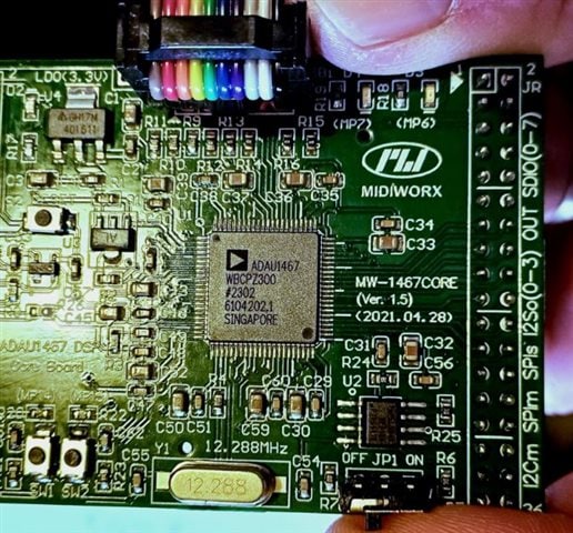
Hello Pierlulgi,
You're on the right track -- studying your ins and outs (ADC, DAC, and MP pins if used) will likely lead to a solution. Of course, the first place to look is any docs from the board's manufacturer. The ADAU1701 Data Sheet can help should you need to do some reverse engineering. You can make simple projects to help sleuth out some info. For example, a project with just an oscillator feeding the outputs can help you find them, even if the inputs aren't working yet.
Best regards,
Bob
Dear Bob in the end I preferred to use a pair of ADAU1701, the 1467 is a great chip but too complicated and it does not have the DACs on board, I should use external ones.. for my project too complicated.. Finally I managed to obtain a perfect modulation on each of the side bands, now I have to find a way to demodulate it. :) The simple product between carrier and signal is able to reveal the signal but is not suitable for isolating the single side band. Probably in this case I will have to use the Hilbert transform too. I do not know if it has already been done before by someone.. will it work?
bst rgs,
pierluigi
Hello Pierluigi,
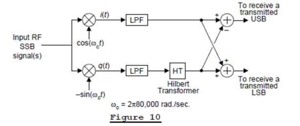
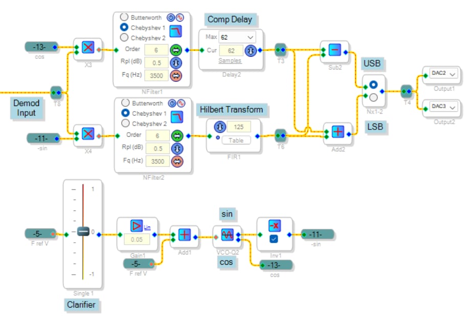
The phase method of SSB demodulation is essentially the reverse of the modulation method. Thus, we do need a Hilbert Transform to accomplish it. In fact, we need two of them -- one to actually perform the transformation (a 90-degree phase lag), and the second one to adjust for the group delay of the first one. The theory is described in this blog post by the legendary Rick Lyons, author of Understanding Digital Signal Processing. The relevant block diagram is reproduced below:
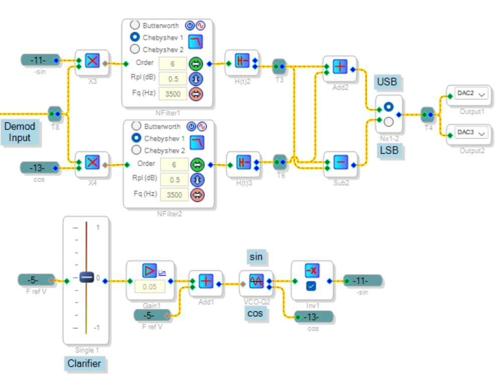
I translated this into SIgmaStudio blocks, producing a SSB modulator - demodulator like the previous one. Due to instruction limitations, I had to run it at 48K, with a carrier frequency of 12 KHz. and a voice bandwidth of 3.5 KHz. The demodulator portion of this circuit is shown below, while the whole circuit is attached as well:
SSB-Mod-Demodulator2.dspproj
This circuit doesn't match Mr. Lyons' diagram exactly; in fact, it appears that the LSB and USB selections are flopped. Yet it works as shown.
There's more than one way to achieve the Hilbert Transform. The ADI Hilbert uses internal feedback (known as IIR, the Infinite Impulse Response method) to work its magic. IIR economizes on instructions while working over a wide frequency range. But the delay it adds to the signal path varies with frequency. This is why the ADI Hilbert has two outputs -- one is the transformed signal; the other is merely delayed the same amount. Our SSB demodulator needs one transformed signal as well as a different non-transformed signal of identical delay -- available only with a second Hilbert block. The resulting unused outputs amount to wasted instructions.
We could choose instead to make a Hilbert Transform with a FIR (Finite Impulse Response) filter. Without the advantage of feedback, these filters can get huge if bass notes need be handled. But they are quite manageable for voice bandwidth. More importantly, the FIR Hilbert's constant delay is easily compensated with a simple delay block -- this uses few instructions. The other problem is we need to design the FIR kernel (list of tap coefficients) ourselves. The attached spreadsheet handles this.
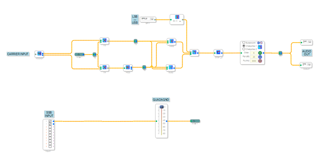
What I found most interesting with this implementation is that unlike the previous one, its logic follows Mr. Lyons' diagram exactly. Perhaps it's because he used a FIR Hilbert in his implementation. The ZIP file below contains the FIR project as well as the kernel calculations.
SSB-Modulator-Demod.zip
Best regards,
Bob
Dear Bob thank you so much for the detailed and precise instructions!
I'll try these tips in the next few days.
Best rgs,
pierluigi
Dear Bob, I finally found some time to dedicate to my project.
One small step for man,.. it works that is, it can demodulate the signal from a single sideband modulation but there is a trouble in paradise as Mr Rick Lyons said..
The circuit it is unable to separate the lower band from the upper band.
In other word both if I drive this demodulator with a voice (modulated in lower side band for example) the output demodulate the voice even if the other band is chosen. I can't figure out where to introduce a real filter that can clearly separate the two bands.
I will continue my studies but it seems like an uphill road..
bst rgs,
pierluigi
Dear Pierluigi,
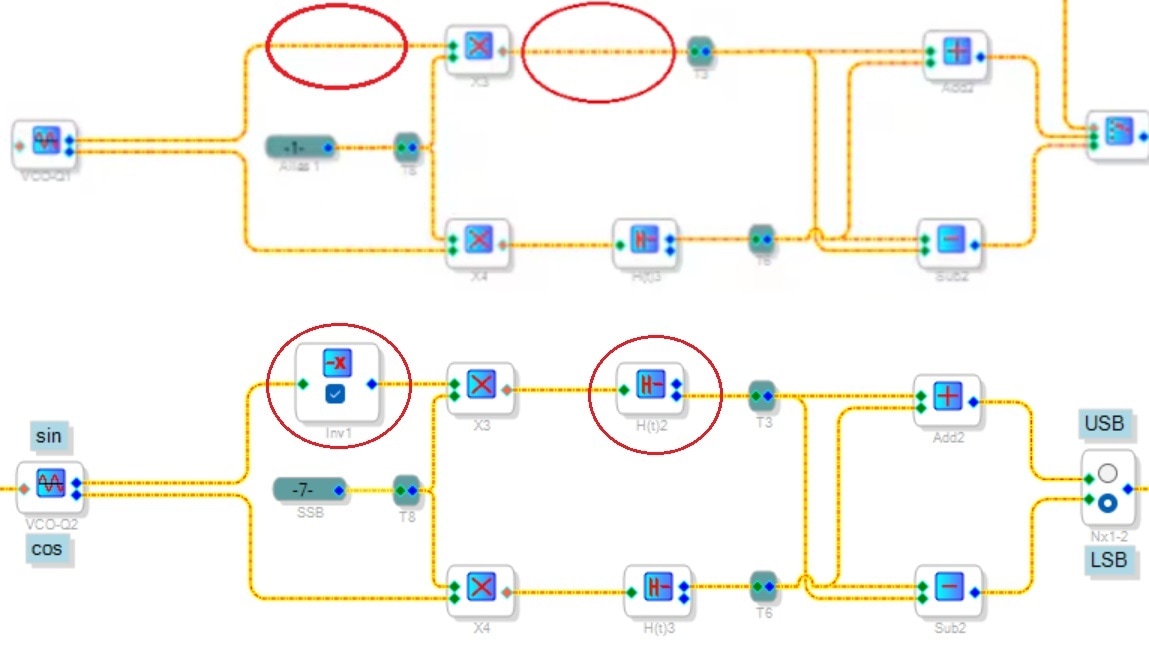
Happily, your road may be quite easy. We only need add two blocks that are presently missing. I reproduced the relevant portion of your screenshot below, circling where the blocks need placing. Directly below is the corresponding circuit from the project SSB-Mod-Demodulator2, rearranged to appear like your project:
The inversion block implements the minus sign in Rick Lyon's example. Why we need the extra Hilbert Transform takes a bit more explanation.
The "HT" block Mr. Lyons shows is a theoretical, perfect one. It provides the needed 90 degrees phase shift over the entire frequency range without any additional delay from input to output. However, a DSP implementation does introduce a group delay, which adds more phase shift that varies with frequency. The SSB demodulator requires an exact 90 degrees phase shift, thus a DSP Hilbert Transform cannot work on its own. We need to introduce a matching delay into the other path without the HT. An FIR HT's group delay is a known constant so we can match it with an ordinary digital delay. On the other hand, ADI's Hilbert Transform is an IIR implementation, whose group delay varies in a complex manner with frequency. To solve this problem, ADI included a second, non-transformed output of identical group delay in their HT block. We must use it to give our demodulator the proper phase shift to work.
Include the 2nd Hilbert Transform and Signal Invert blocks exactly as shown, and you'll be having fun at last.
The demodulator as shown above has no IF or audio filters. In this form, the entire SSB modulator-demodulator uses 474 instructions, thus happily runs at 96K. Of course, a version that functions with real-world interfering signals would need filters. Thus, your idea to use two -1701's will come in handy. Where I work we market a PA mixer with fully six -1701's interconnected via I2S / TDM, with a PIC uC running the show. We did it this way for reasons similar to yours: My associate Mike and I are already familiar with the -1701, it has built-in converters, we get a price break on the larger quantity needed, and Mike's PCB layout works out neatly. Mike also wrote nearly all the PIC's C-code while I did the SigmaStudio stuff and some filter coefficient math.
Best regards,
Bob

Hi Bob, first of all I apologize for taking up your time, but unfortunately, I fear I've hit a dead end. After hours and hours spent trying to get the demodulator working, it still doesn’t work...
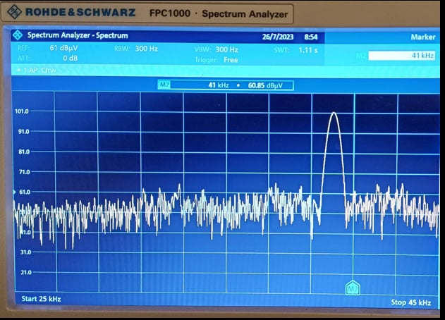
In my project, I’m using two ADAU1701, one as a transmitter and the other as a receiver. The transmission modulation seems perfect, both in LSB and USB. The carrier is 41Khz:
However, the receiver cannot separate them. I’m using a 96 kHz frequency and a program length of 2x instructions.
In fact, when I set it to LSB, I don’t receive anything at all. Unfortunatly I lack the mathematical foundations to fully understand how it works, at least theoretically.
I tried to add the block(s) you suggest but unfortunatly it doen't work.
Mi goal is to obtain two separate channels using the same carrier frequency of 41Khz, at this point I'm starting to think it's not possible..
thanks for your help
bst,
pierluigi

DaveThib said:
Bob has managed to do some amazing things with the 1701. You would be wise to follow him and look up some of his older posts. There is a reason he is designated a Super User!
Hello Dave,
I just noticed your compliment above. Thank you so much!
BTW, your YouTube channel is a fine idea. If a picture is worth 10^3 words, a video must be worth 30 x (t) x 10^3 words!
Hello pierluigi,
I think your carrier frequency is too high for the sample rate.
If you read what KJBob had explained in his example he was running at 48kHz fs and was using a carrier frequency of 12kHz. This is 1/4 fs. You are running at 96kHz and using a carrier frequency of 41kHz which is just barely below the Nyquist of 48kHz. So you are close to 1/2fs.
For an experiment I would try a carrier frequency of 24kHz and see if that works. 41kHz has too few samples to represent the waveform so the gain error will be huge and vary quite a bit.
Dave T
Hello Dave and Pierluigi,
Please don't worry about 'wasting my time,' I'm truly sorry about wasting yours since it's yet to run for you. I've been thinking about why it works here and not there. One important reason -- so far, my test projects had the modulator and demodulator all on the same chip, with the signals never leaving the mathematical precision of DSP. Although you haven't described your ultimate application, I assume you wish to send a SSB signal at point A and receive it at point B. Thus, the whole idea is only useful if we can split the mod and demod onto separate -1701s like you mentioned. Will it still function after subjecting the modulated signal to the phase shifts of those oversampled ADC and DAC filters? So, mostly out of curiosity I went and tried it.
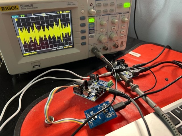
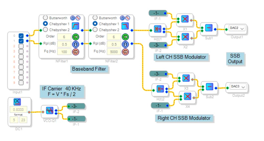
The modulator is running on the rightmost ADAU1701MINIZ eval board below. After downloading the project, I wrote the compilation to the board's E2PROM. This way, I could power it from a 6V power adapter (the same one which ships with ADI's -1452 board). Had some trouble getting it to write and self-boot, yet eventually it produced a modulated waveform. See the scope below (I don't have a spectrum analyzer). Rather than have a USB-LSB selector, I made the thing stereo -- the left input produces LSB modulation on the left DAC channel, the right one makes USB on the right DAC. Normally one would mix the upper and lower sidebands to mono and filter them apart at the other end -- I didn't bother but could try that if asked. Edit: This works too. The demodulator separates the mixed LSB and USB signals, even without pre-filtering.
The eval board at left is serving as the demodulator. Both boards are running at 96K sample rate. Surprisingly, it works as well with a 40 KHz carrier frequency as with 24 KHz. Dave's comments about running near Nyquist are of course true; many ideas suffer up there. For example, a digital integrator falls apart above Fs / 4. Yet, in this case we're getting away with it. Please don't ask me to explain the math, I only know DSP from reading books and playing with SigmaStudio. Anyhow, I'm listening to the processed result as we speak. It sounds like AM radio, yet in glorious stereo!
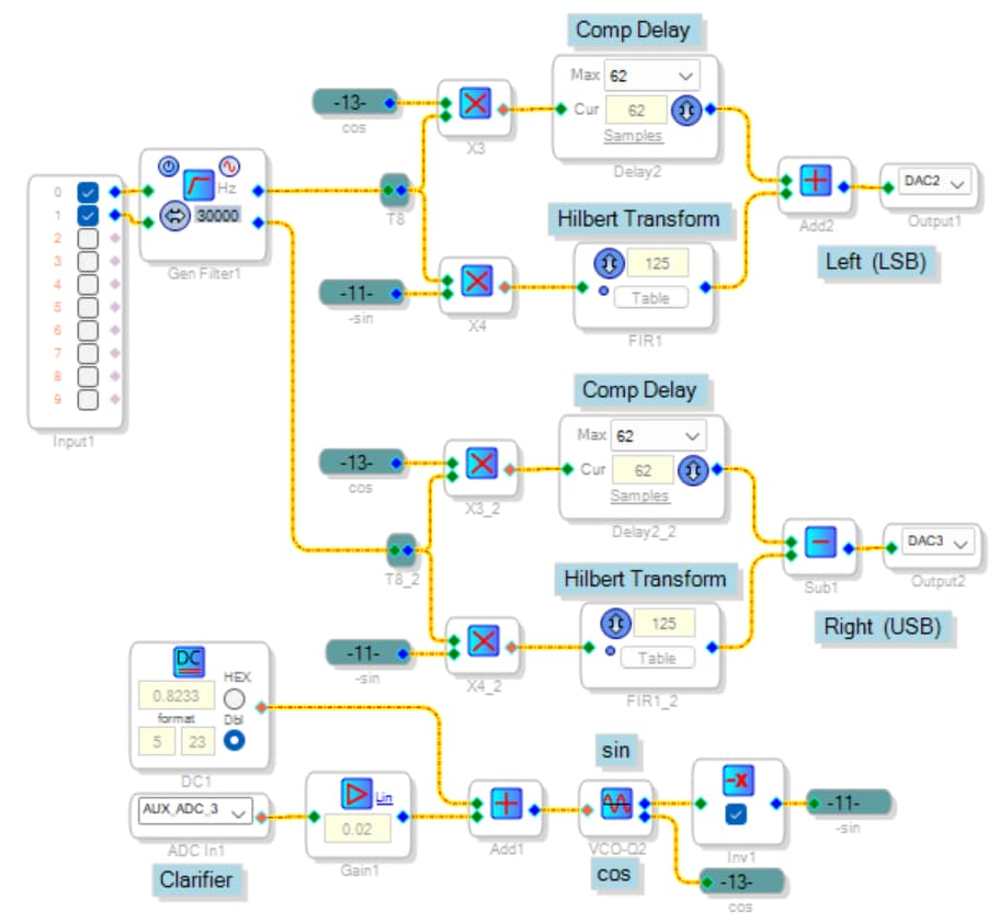
The modulator uses ADI's Hilbert Transform. For the demodulator I opted for FIR Hilbert filters since they're more economical. Both projects use about 400 instructions, thus run fine at 96K with room to spare. The two projects are shown below as well as attached.
Stereo-SSB-Mod-Demod-40KHZ.zip
Well, this is about all I can do to help with this endeavor. I could end with a plug for ADI's evaluation boards -- when you're trying to invent a solution, the last thing you need is unknown, sketchy hardware. Unfortunately, the ADAU1701MINIZ is expensive for what it is. I should know, I work for a contract manufacturer.
Best regards,
Bob
Hi Bob, thank you so much for the work you've done! I'm sorry for having made you waste all this time... I tried, and in the end, I managed to achieve a satisfactory result. WOW
Thank you so much, truly. If you happen to pass through Florence, I’ll treat you to a lunch.
I would think that the problem at this point was within the Hilbert transform block present in Sigmastudio. By using the FIR filter now the behavior is significantly different.
Still difficult, though..
I use these modules, they are very cheap and they works very well: tinyosshop.com/tsa1791
The ADAU1701MINIZ is too much expensive for me.
Please log in to reply.