ADAU1452 - SigmaStudio+ fails to program the self-boot memory.
Hello,
It appears that the settings for the EEPROM block in SigmaStudio+ are non-functional.
Even if I set the chip erase cycle time to 50 seconds, it only takes 15 seconds for the whole programming process to finish.
SigmaStudio+ will program the ADAU1452's SRAM and clear its self-boot memory, but it won't actually write to it.
I am using a development board off of AliExpress that has been modified to use the EVAL-ADAU1452MINIZ's SPI EEPROM for consistency's sake (25AA1024-I/SM), along with a pre-v1.5 USBi programmer.
I have tested the board with SigmaStudio 4.7. It works perfectly fine.
I have tried to hook it up with both the EVAL-ADAU1452MINIZ platform, as well as a "custom platform" configured appropriately, but neither worked.
Any help would be greatly appreciated.
Best regards,
Edwin
Audio Signal Processors
adau1452
software
SigmaStudio+ v2.0.2.2
SigmaDSP Audio Processors
Hello Edwin,
Can you attach your project?
Thanks for checking that Rev 4.7 works fine on that board. That is really helpful. This also tells me you know how to perform the EERPOM programming.
I will investigate.
Thanks,
Dave T
Hello Dave,
The file is attached below.
Best regards,
Edwin
NewProject.ssprj
Hello Edwin,
I guess the self-boot only works with the default control register settings, it fails to write the control register values as we configured in SS+, So all the control registers are with their default value. sorry for that, it's a bug.
I see the TDM8 out in your project, but that setting wasn't written at all. Even you can't make an LED blink with self-boot since it requires MP pin register configuration, you can put it in MP mode and blink an LED and it will work while you link compile download, but during self-boot it acts as a primary pin since the control registers weren't written in self-boot mode.
So please try the self-boot procedure with the below project, the project only has an audio pass thru program with default register settings (just an I2C in and out). it works for me in self-boot mode.
Just an I2S in from serial input port 0 (ch 0-1) to serial output port 0 (ch 0-1).
selfboot_default.ssprj
can you please try this and get back with your results? so, we can confirm this phenomenon.
This bug has been noted and reported to the respective team. Sorry for the inconvenience caused.
Regards,
Harish
Hello Harishgowtham,
When I read the EEPROM using SigmaStudio+'s display tool, it reads all 0s, so that program is also not getting written.
The default behavior of the DSP is to route all serial inputs of the DSP to all serial outputs, so it will appear that the program is getting written to the EEPROM, but it actually isn't at all.
You can check this by reading the register values after cycling the power of the device.
In my example, I am summing the serial input with the SPDIF input; I used this signal path to verify that the configuration wasn't retained.
This problem definitely exists.
Other people are having the exact same problem (see here).
The other thread was marked as answered, but the problem was never fixed.
People are still periodically pinging the thread because of this, but no one has replied.
Best regards,
Edwin
EDIT: The problem still persists on SigmaStudio+ v2.3.0.
Hi Edwin,
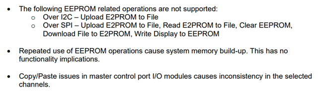
There is a limitation in SigmaStudio+ with respect to the EEPROM, which we mentioned in the SigmaStudio+ 2.3.0 release notes: C:/Analog Devices/SigmaStudioPlus-Rel2.3.0/AE_46_SSPlus_ReleaseNotes.pdf.
Thanks
Hello Edwin,
I have seen the thread you attached.
Self-boot with SS+ behaves a little different for me. I use version 2.1.0 , below is how it works for me.
Edwin said:
When I read the EEPROM using SigmaStudio+'s display tool, it reads all 0s, so that program is also not getting written.
I'm not sure how did you read the EEPROM data. Did you try reading it from SS+ via USBi? It won't work since the USBi and the EEPROM has no direct connection. SS+ writes a data server program to DSP then the DSP transfers the self-boot data from slave port to master port, the DSP's master control port writes the self-boot data to the EEPROM. The EEPROM is connected to the DSP's master control port. The EEPROM's CS pin is tied to SS_M/MP0 pin of the DSP. So, there is no way you can read the data from EEPROM via SS+.
Edwin said:
The default behavior of the DSP is to route all serial inputs of the DSP to all serial outputs, so it will appear that the program is getting written to the EEPROM, but it actually isn't at all.
The program Data (schematic that you design) and DM is also properly sent to the EEPROM but the changes that you make in the control registers doesn't make it thru, hence the DSP uses the default value for those registers. Since all control registers (Important control registers: PLL, SPORT, ASRC, SPDIF, MP, CG etc.) use their default value, the configuration you did doesn't make it thru. Hence it doesn't work.
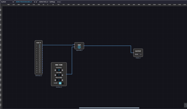
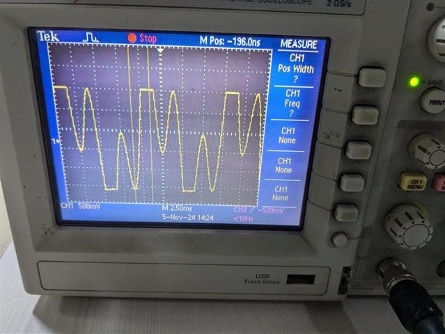
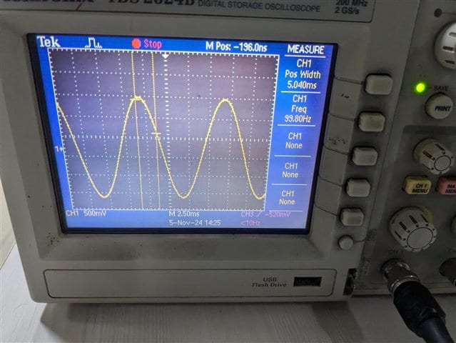
Here is the thing I tried; I sent a sine wave at 300Hz via SPDIF from one board. I received the SPDIF signal (of course by configuring registers in the ROUTING_MATRIX) in board 2 and added another sine wave of 100Hz and sent it to output. Below is the schematic and output when I link compile download. The output is expected.
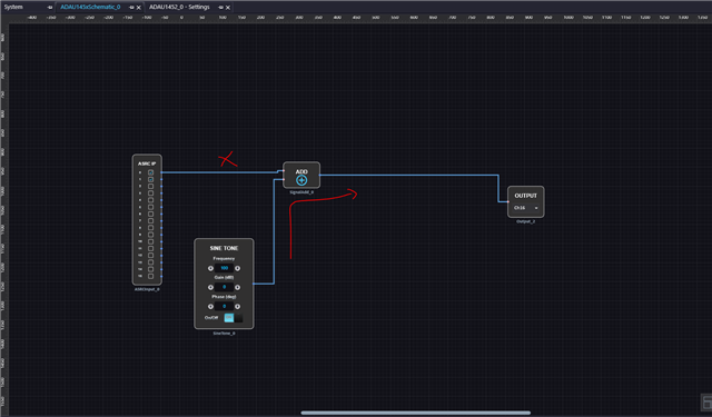
when I write this program to the EEPROM by using 'write latest compilation thru DSP' and power off and on the board and turn on the self-boot switch and hit reset, I can only see a 100Hz sine output and the SPDIF input didn't make it thru since the ASRC registers in the Routing matrix weren't programmed as I configured. Hence only 100Hz is being output by the schematic.
It's an issue anyway, I will pass this info to the respective team.
Regards,
Harish
Hello ChiruPalle,
The release notes do not mention not being able to Read EEPROM to Display, but even if that's the case, Check Latest Compilation Through DSP also fails and reads 0s in the Capture logs.
Best regards,
Edwin
Hello Harishgowtham,
After testing the EEPROM again, it seems that I am now getting no audio through the device when running from the self-boot memory.
It is very interesting that on your board it seems that the ASRC registers weren't configured correctly.
I can't verify this, because my system is 8-channel TDM and the SDATA registers don't retain their config on startup, but that could explain the problem.
Still, when I Check Latest Compilation Through DSP, it says Self-boot check failed, so the EEPROM is most-likely not being correctly written to.
Best regards,
Edwin
EDIT:
I hooked up a sine wave to the output of the ADAU1452 and wrote it to the DSP.
When I cycle the power and read the Core Control settings, the core is stopped, so my setup definitely behaves differently in that respect.
Hello Edwin,
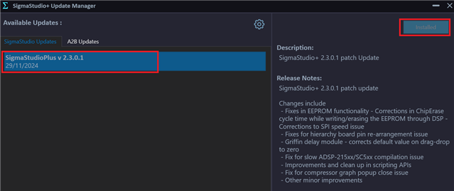
I was informed by the programming team today that they have fixed this issue and some other EEPROM issues with the latest revision. It is now available.
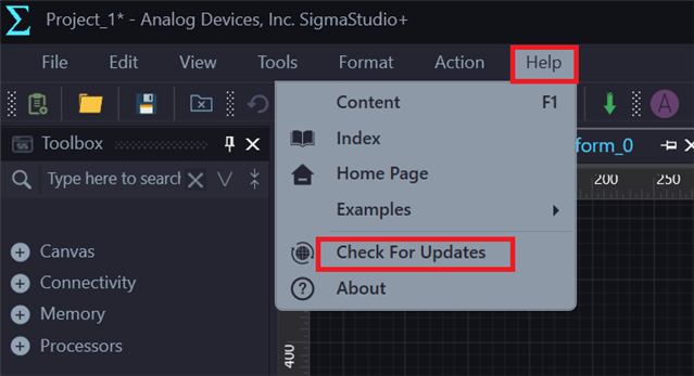
Please update to SigmaStudio+ 2.3.0 Update 1 using the SigmaStudio+ Update Manager (Help Menu -> Check for Updates).
If you are still facing the issue, please share the schematic.
Thank you for understanding.
Dave T
Please log in to reply.