Muting with adau1701
Hi guys, I'm trying to learn how to use sigmastudio through online guides but I can't find all the explanations based on the functions that are there.
Also, many times I don't know what a function is called and I spend a lot of time looking for it.
Let me explain my problem:
I need to create a mutig at power on and power off.
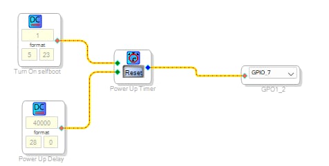
I found an example online but it only works at power on and not very well.
I want that when the ADAU on GPIO_7 is powered after 5sec it gives me 0V output
at power off, as soon as the ADAU on GPIO_7 is turned off it must open the contact because on the circuit I have a pullUP of 3.2v and therefore the line immediately goes to 3.2V.
How can I do this in my project?
I attach the example that I found only for the power on
Audio Signal Processors
software
Sigma 4.7
SigmaDSP Audio Processors
adau1701 sigmastudio
muting
Show More
Hello dstitlab,
This is not a trivial thing to try to do. It will take some study of what happens when power is first applied and when power goes away. I am not talking about the DSP alone but the entire circuit. I do not know how you are actually muting the audio.
In addition you mentioned powering off yet you talk about having a pull-up to 3.2V. Well, if power is turned off then the 3.2V will also go away? So what exactly are you doing when you power off and on? Do you have the 1701 driving an external amp? Does it have a muting function?
Ultimately this is all best done outside of the DSP. You need to have some advanced knowledge that power is going down. Is that available in your system? I have seen some people take the power through a diode to isolate it and load it down with a small resistor and cap to have it not stay high for long. Then, the feed to the DSP is also through a diode where it has a very large bulk capacitance so it will hold the voltage for much longer. The idea here is to develop and "power going down" signal from the small RC to signal the DSP that is being kept on by the large RC circuit.
This all comes down to lots of trial and error and adjustments to give the DSP time to mute the audio.
Here are some more of my thoughts on this.
For power up it is best to have the external to the DSP outputs muted by a low logic line. So at power up it will be muted. Have this logic line pulled down not up. Therefore keeping it muted as power comes up and will remain muted until driven high.
Now, changing my focus to the DSP. The GPIO outputs are pins that are multi-function which will default to an input with a high impedance. This means it will float high! It will float high before the DSP wakes up, is programmed and then does something to change the pin to a GPIO and set the correct output state. WAY too much time!
So the idea I have always done is to have a transistor to invert the logic on the pin and have it pulled up. So when you power up it will float high and turn on the transistor and ground the collector and that should drive the mute circuit where a low is the muted state. Then when the DSP wakes up have it setup the pin as a GPIO and have it set the state to a high output. This should prevent and glitches in the output of the pin. It should stay high. Then with the timer like you had done you time it to go low after 5 seconds or so.
This sort of attention to detail and plenty of scope captures you should be able to get the power on to be stable and be off until the DSP is awake and unmutes the audio.
For power down then use a different circuit to take in a GPIO input from the small RC circuit I described earlier. I suppose you could use an AUXADC and program in a threshold. If the voltage goes below X then change the GPIO output to a high to mute the output. Remember I described the GPIO high as muted and low as unmuted.
By the way, this assumes whatever amp you are using has a clean and quiet power up and down. The DSP may not be the problem.
If you have a system controller sometimes it is possible to get a power-good signal from a regulator and have the system controller handle the mute and unmute.
As you can see this is all a bit of an artwork and a study on details. There are too many variables outside of the DSP so this will require you to work out these little details. Ultimately a lot of this falls outside of the DSP because the DSP takes a while to "wake up" and when the power is going down the DSP stops in its tracks and cannot do anything. We do have this feature where the 1701 can writeback to EEPROM to save up to eight settings but for this to work you have to work out a trigger using the small RC network and a large RC "battery" to keep the DSP alive long enough to complete the writeback before it loses power.
As you can see by my long response, this is not trivial.
I hope some others on the forum can offer advice where they have done this.
Dave T
Hi Dave,
Thanks so much for the very detailed answer.
My circuit sends the SD pin of the pwm to GND through a BC846 transistor, so when the MP pin of the ADAU1701 goes to 0V, the amplifier will work correctly, when the MP pin is high, the amplifier will go into MUTE.
For shutdown, I have the possibility of taking a feedback from the PSU and configuring a GPIO and with an AUXADC I can program a threshold to obtain a High level output and therefore amplifier in MUTE.
The problem is that I do not know how to use all the functions of the sigmastidio well because only at the beginning, are there any example files?
I think that the more I use Sigmastudio the better I will know how to configure my project.
If there are example projects, I thank you in advance, otherwise I will dedicate all the time necessary to achieve my goal.
Thank you all so much :)
Hi Guys, sorry for my absence but I had to spend some time to start learning sigmastudio and I confirm that it has many fantastic functions.
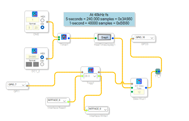
For my recalibrated ignition I solved as per attachment, and it works correctly.
But I have not found a converter from sec to hex to easily insert the code.
Now I need to check the rms voltage of GPIO 7 and verify that it is always high and as soon as it drops below a threshold, it must be added to my muting section and switch GPIO10 to High level.
I attach my project but I can't find the right functions... what can I do?
Please log in to reply.