Using SDATAIO pins for a large number of I2S signal lines.
Hello Harish
I have some questions about adau1467, how I could use SDATA IO0-7, any examples? I need 16 i2s in and 16 i2s out. or should I start another topic to ask this question?
Best regards,
Power Pan
Edit Notes
Split off this post, changed the title and edited the text down to the relevant question for the topic.
[edited by: DaveThib at 5:44 PM (GMT -5) on 7 Jan 2025]
Audio Signal Processors
SigmaDSP Audio Processors
Hello Power Pan,
PowerPan said:
BTW: I have some questions about adau1467, how I could use SDATA IO0-7, any examples? I need 16 i2s in and 16 i2s out. or should I start another topic to ask this question?
Yes, you should probably split this off onto another thread. I might see if I can do that myself...
Anyhow, Do you mean 16 stereo I2S signals or 16 channels of audio in I2S format? So there would only be eight I2S signal lines? Then you also mentioned inputs and outputs. So 16 I2S lines in AND out? That is 32, I2S connections. Wow, that is a lot.
This makes a huge difference. If eight I2S lines is what you need then you can do it with two parts. If it is 16 that you need then you will have to use four parts to do it and use one of the serial ports to send audio between the parts. I assume that would be needed.
I will attach my starter project for the EVAL-ADAU1467Z which uses the SDATAIO pins for the codec inputs and outputs.
This shows the basics of how to setup the registers but it is not using all of them.
Designing the signal flow with 32 I2S lines will be tricky and a challenging PCB layout. Sounds like a fun challenge!
ADAU1467 IO routing and settings for Rev B eval board.dspproj
Hello Dave
thanks for the reply and sorry for my unclear question.
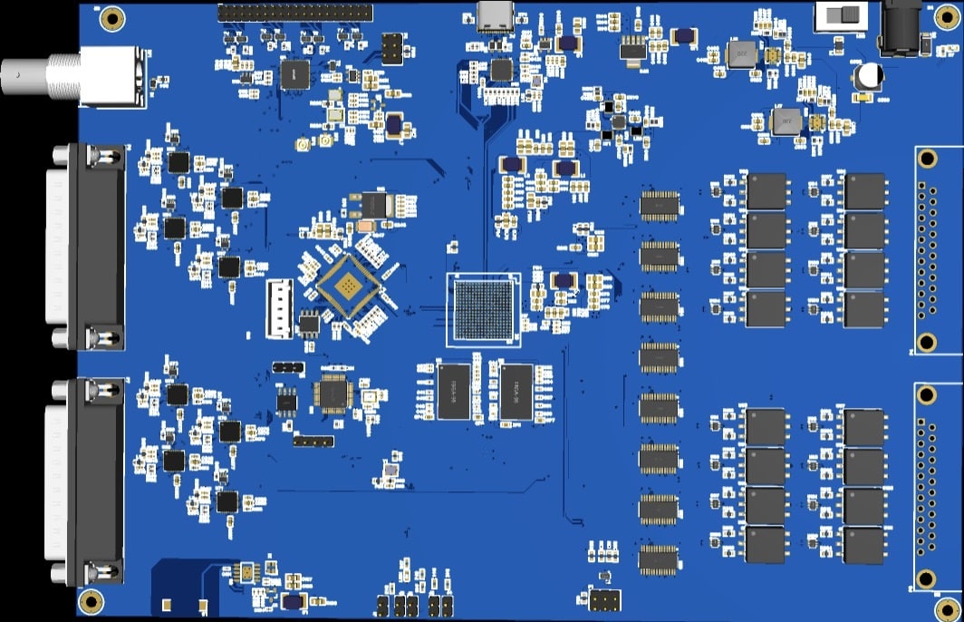
I need 16 ch i2s in with 8 pins, and 16 i2s out with 8 pins, as the 3D PCB shows, this is a board to do post-processing for RME pci-e sound card to do the room acoustic correction with delay/gain/equalizer, etc.
I checked the attached file and finally figured out that the pin setting is in TAB serial_port->SDATA IO but all SDATA IO could only choose TDM instead of I2S, my question is how could I config 4 SDATA IO as input I2S and 4 SDATA IO as output I2S?
Best regards,
Power Pan
Hello PowerPan,
There are a few weird little details to tricking the serial ports to take in more than two channels. So some of the settings will say TDM4 but you just need to clock it with a I2S bit clock rate and it will work.
With the number of pins you need you will have to use two parts. I am not 100% certain what the best way to split it all up will be but I think it will be one chip processing all the inputs and one processing all the outputs. There are a lot of little details to work out. It will be best to draw up a system diagram. Also, what will be the clocking? I assume the sound card will be synchronizing with the internal computer clocks and so you will need to operate the DSPs as a clock slave. The good news is that with having to use two chips you gain another set of sample rate converters so you can use them in both directions.
There will be a lot more questions on how to set this all up. Start new threads. This one is getting a little long.
If you give me a detailed diagram I will try to find the time to whip up a project that has the basic setup.
Dave T
Hello Dave
I'll start a new thread and attach my basic diagram with the project file; it could save your time setting up this.
Best regards
Power Pan
I think if I need 2 1467s I'd rather use adsp1802.
Please log in to reply.