Index Selectable Filter - what is the purpose of the number of biquads?
Hello all,
I am trying to understand what the number field in the index selectable filter is for. According to the documentation it stands for the numbers of biquads, but what exactly is meant by that?
My intuitive thoughts are that this number represents either the number of cascaded biquad filters or the number of an internal loop repeatedly running the signal through the block. From the description of the block in the documentation I would think it's the latter, as the purpose of this block is saving ressources and looping the signal through the filter would likely be more efficient than implementing the filter multiple times.
Both ways of operation would result in the effective increase of filter order in the way of 2^N, where N would be the number of biquads.
However, when I change the number and reupload the program to the DSP absolutely nothing changes. The impulse and frequency response of the filter stays exactly the same.
I am using SigmaStudio 4.7
Am I missing something?
Audio Signal Processors
software
sigmaStudio 4.7
SigmaDSP Audio Processors
adau1466
Hello JHe,
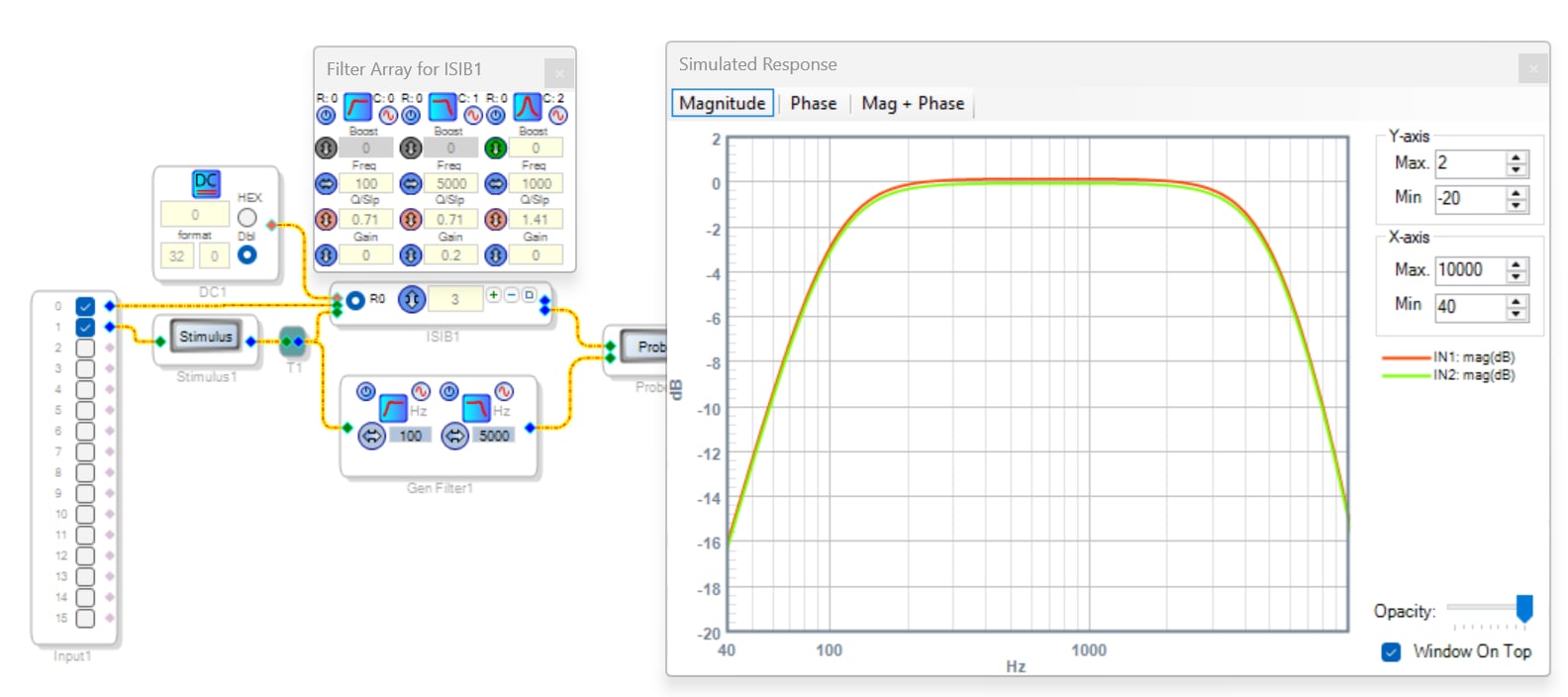
This block has many moving parts. Clicking the tiny square at the end of each row shows the filter(s) in that row. The block runs through a given filter cascade just once. Thus, this block and the General filter of the same parameters produces identical curves, as shown below. As you noted, the number you type into the box lets you choose how many filters are included in each cascade. When you increase the number of filters in a row, the added filter(s) default to parametric filter(s) of zero boost -- thus with no effect upon the block's response.
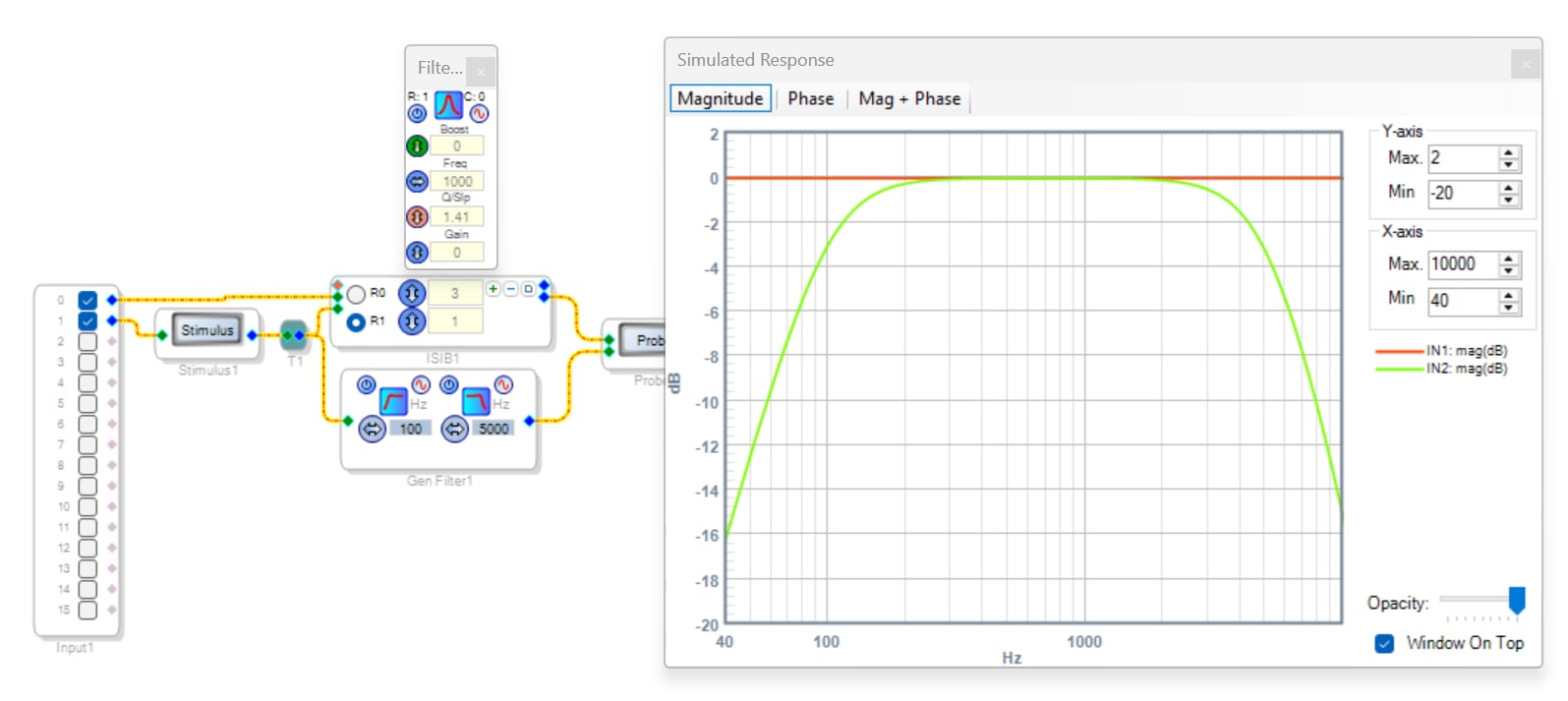
Clicking the + button adds another row to the Index filter table, where you can select between your curves at runtime by inputting an integer (32.0) index number at the red pin. This is the main idea of index filters -- SigmaStudio pre-calculates the sets of five coefficients that each biquad needs, stores them in parameter memory, then the DSP recalls them according to the selected index. Otherwise, we would have to make individual filter strings and choose the desired one by a Mux. I'm not sure about the -1467 which is an advanced part, but in the ADAU1701 and similar, the project would waste instructions on the non-selected filters. The index runs from 0 to (N-1), not (1-N) -- exceeding the (N-1) limit pulls random stuff from parameter memory, with rather fascinating results. Below I added another row with its default setting of one no-boost parametric filter. Selecting the button (R0, R1...) at left of each row chooses what filter shows up on the Stimulus-Probe display (which ignores your input at the red pin). You need not compile or use hardware to work the Stimulus-Probe tool, which runs complex math to compute a predicted response. For more info on Stimulus-Probe, see this document.
This is definitely one block where the Wiki could use more detailed instructions with illustrated examples. I've only attempted to edit the Wiki a few times -- it's rather difficult as with nearly any wiki. Besides, all my edits have remained as drafts and never approved. So much for that.
Best regards,
Bob
Hello JHe,
Yes, I think you may be making this more complicated than you need to be.
The index selectable filter will select between "X" amount of filters. You define how many filters. So let's say ten. So this means you give it an integer number between 0 and 9 and it will apply the corresponding filter. The program will use the correct set of coefficients, it will not calculate ten filters, only one and the one it calculates depends on the number coming in on the control pin. It MUST be an integer not an 8.23 number! This integer number is used as an offset to a pointer address so if you give it a number out of range it will go to an invalid memory space and pick up whatever is there.
The problem with your program not changing will have to do with how you are controlling the filter. You did not include your project so I have no idea what you are doing wrong. Here is a project I wrote for the Sigma300 cores that uses an AUXADC to control a filter.
I am dropping in two programs that are slightly different. One uses a table.
7077.ADAU1452 AUXADC Controlled Index Selectable Filter.dspproj
ADAU1452 AUXADC Controlled Gain via an index controlled table for custom values.dspproj
Dave T
Thank you very much, Bob! This is the answer I was looking for. From the documentation it is absolutely not clear that by increasing the numbers of biquads there are *new* and *individual* filters added.
Since it is mentioned nowhere, I was under the assumption that the block worked by basically copying the first filter in each bank:
Set filter parameters -> increase number of biquads -> filter gets cascaded with each element being the same filter/being a copy of the first
when instead it works like this:
Set number of desired biquads -> set parameter for each one manually
I will give my program another go with this new info on how the block works.
Thanks again.
Hi Dave, thank you for the response. My problem was not with the block not sliding through different sets of filters via index (this part worked for me from the start) but with the number of biquads in each filter bank.
Bob has provided the answer I needed. An update on the Wiki should really be considered imho as the behavior really is not obvious and this block has a lot of potential. Thanks!
Please log in to reply.