ADC input with unexpected value
I am working with an ADAU1450 and use 4 ADC inputs as volume control.
If the volume control is full open I will have 3.25V DC on my ADC_0 input of the DSP.
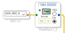
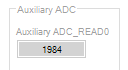
But when I read the value in the software I find a value of "1984" in the hardware page.
From the data sheet I get that the AD converter is a 10bit converter (so max of 1024 steps).
How can I get a value of "1984" on my input? I would expect a value of max "1023"
(Or almost one, after bit shifting, as David describes in his excellent video)
Where do I go wrong?
Audio Signal Processors
adau1452
software
Sigma Studio 4.6
adau1450
SigmaDSP Audio Processors
Show More
Hello Huib,
Could you please attach your project and hardware schematic?
We will have a look and get back to you.
Regards,
Harish
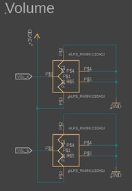
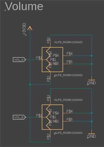
Attached the file and schematic for the volume. Vol_A is connected to the ADC_0 input of the DSP
DesignADAU1450.dspproj
Hello Huib,
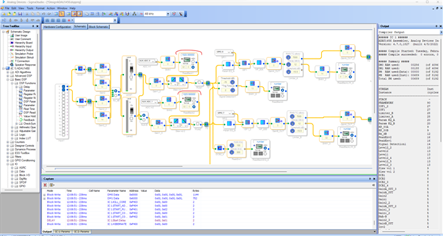
Your project works fine with my Eval board. So, it should be something with your hardware connections.
The potentiometers on the Eval boards are 10K ohm.
The picture that you attached is not quite readable. Can you please attach a clear picture and mention that part's name?
Regards,
Harish
HI Harish,
First of all thank you for looking into this.
The part used is: https://www.digikey.com.au/en/products/detail/alps-alpine/RK09K1110A0J/19529183?s=N4IgTCBcDaIEoGkAMBOBBGTSCCSBSIAugL5A
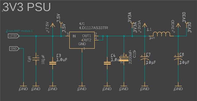
If I measure on the on the ADC_0 input pin (pot full open) of the DSP I find 3.25V DC. AVDD is 3.32 Volt DC
This should translate into something around the 1000. Nothing over 1023 anyway. I get 1984 on the RAW reading of the DSP core.
Do I need to terminate the other ADC inputs? They are floating at the moment. ONly 0 and 1 are used at the moment
I have done the same setup on my ADUA1467 eval board (that I used to design my project) and that works fine.
Again thanks for your time.
Huib
First of all thank you for looking into this.
The part used is: https://www.digikey.com.au/en/products/detail/alps-alpine/RK09K1110A0J/19529183?s=N4IgTCBcDaIEoGkAMBOBBGTSCCSBSIAugL5A
If I measure on the on the ADC_0 input pin of the DSP I find 3.25V DC. AVDD is 3.32 Volt DC
This should translate into something around the 1000. Nothing over 1023 anyway. I get 1984 on the RAW reading of the DSP core.
Do I need to terminate the other ADC inputs? They are floating at the moment. Only ADC_0 and ADC_1 are used.
I have done the same setup on my ADUA1467 eval board (that I used to design my project) and that works fine.
Again thanks for your time.
Huib
Hello Huib,
This is strange Twilight-Zone kind of things!!
I just pulled out my eval board once more and tested it with the settings you have and this is what I see:
You see the lower Readback is the raw data not shifted. I got 1022 as a max.
I am wondering if this might be an issue with the USBi and the SPI comms having errors?
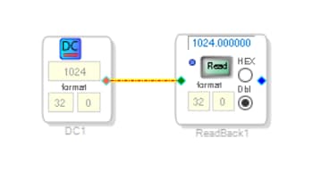
Put in a DC cell, set it for 1022 or 1024 something like that and connect it to a readback and see if it reads correctly?
Like this:
Attach your project as Harish asked and there may be some clues in there for us.
Thanks,
Dave T

Hi Dave,
Thank you for looking into this. The file is attached to the reply message to Harish. He was able to open it and had no problems.
I have transferred my file to my ADAU1467 EVAL board and no problems there. Reading is 1022.
The voltage on the input of the ADC_0 of my EVAL board and my own hardware are 3.29V DC and 3.25V DC.
I had 5 boards made to test and tested another one but it does the same thing. So if it is hardware related it is my design.
I did the DC to Readback test and that shows like your example. DC 1024 is 1024 on the readback (32 0) (when compiled on my hardware)
But that makes sens as I read a value of "1984" at the hardware page of the core (I use "Read all registers" in the AUXADC hardware page)
The USBi I use is fine with my EVAL board but not sure how I can test this with my setup. I will look into this.
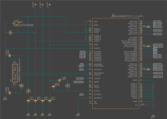
I have tried to use the SPI and I2C of the ADAU1450 in my design but this is not working. I need the SPI pins on the DSP to define a I2C address.
I2C is used for communication with my MCU and I was hoping to use SPI to monitor but that does not work.
With this setup I use SPI/USBi to load the file into the DSP and my MCU is idle but connected to the I2C at the moment.
Could this be a problem? Could it have something to do with a reference I am missing? Sample rates?
Attached some of my schematic. Again thanks for your time.
Huib
Hi Dave,
Problem solved. You triggerd me with the SPI/I2C connection.
Although nothing was running on the I2C bus it messed up the communication.
All was working fine except the readback. So I didn't think it would have anything to do with the SPI bus, but it did.
As soon as I cut the lines on the board it all worked. Sorry my fault.
Thanks for your time.
Huib
Hello Huib,
we are glad that the problem is solved.
It's always recommended to share the full schematic so that we can have a look at all the possibilities for the problem.
All the best for the rest of your project!
Regards,
Harish
Please log in to reply.