SPDIF RCA/Coax interface understanding
Hello EZ,
Here I am with another question thats probably really stupid. I'm a mechanical engineer deeping my toes in audio electronics so please bear with me. I have sucesfully designed a PCB that is effectively just a DSP breakout board which has the ADAU1452/66, a PSU and som ribbon cables for all the i2S and SPDIF signals.
Now its time to make the input and output boards. I think I have the ADC and DAC parts under control, but the SPDIF... For me its a jungle!
Looking at the Eval board and the ADAU1452 datasheet this is my understanding:
The SPDIF pins on the ADAU chips are 0-3.3v (IOVDD) tollerant.
The reciever is centered around 1.65V with a 200mV minimum swing required - Meaning that everything below 1.55V is considdered a 0 and everything above 1.75V is considdered a 1.
The output pin is either 0V for a 0 or 3.3v for a 1.
Is this understanding correct?
On the eval borad, both SPDIF input and output is connected more or less directly to toslink recievers and transmitters.
Looking at their datasheets I would expect that the reciever outputs 0 or 3.3V on its VOUT pin as 0 and 1. The transmitter accepts 0 or 3.3V to generate 0 or 1. This would align with my understanding above.
However, for RCA/coax type SPDIF signal I get lost.. The standard says:
Minimum input level = 0.2V
Output level = 0.5-0.6V peak to peak
How on earth do I make the connection between the ADAU1452 and a Coax SPDIF connector? I see many products using transformers from Pulse to isolate the signal, but I do not understand how to generate the correct voltage levels..
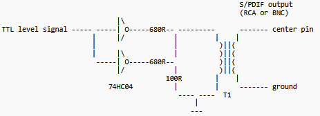
I found this diagram as the only pointer to how it works
Can you point me in the right direction to get a better understanding of how this stuff works?
Best regards,
Daniel
Audio Signal Processors
adau1452
spdif
hardware
schematic
SigmaDSP Audio Processors
Coax
Show More
Hello Daniel,
Your questions are very good and the confusion is certainly understandable and I have had similar questions in the past.
Pulse has some great products and is a good place for info. Note how the diagram you showed has two inverters in parallel. This is common to see because the hex inverters are cheap and using two of them gives enough current to drive the load.
The SPDIF 200mv spec is to deal with losses along the line so there are special circuits, sort of compressors, to be able to properly pick up a small 200mV or much larger signal using the same input. Your numbers around the common mode I think is correct because I think the 200mV is an RMS number not peak. There is a spec for the standards.
This document is good:
Interfacing AES3 and S/PDIF
The transmitter will be a 0V to 3.3V signal but that is in a perfect world, the specs are often hidden in the digital pin specs where a high is around 80 or 90% of the IOVDD voltage. Likewise, a low will usually be something like 0.8V or lower. There has to be a spec saying how high the "low" can be and still be considered a low output. This concept should be super familiar with your mechanical engineering work. Nothing is X-inches long. It is "X" plus or minus.
Have a look at the Rane Note and there are other references listed there.
Dave T
Hello again Dave!
Yes i did look through the forun and saw other similar questions, but needed to get my own understanding verified. I read the document you linked to, and while i did learn a thing or two Im still full of questions.. you know me by now, many questions.. so lets go
So the use of inverters or similar drivers, is that required to drive a coaxial line from the ADAU DSP's? Or is the transmitter build into the chip powerfull enough to drive a coax line directly through a voltage devider and a transformer?
I'm aware of the ideal world vs. real world tolerances. But good to get the voltage levels confirmed. So this means that to go from the SPDIF out of the ADAU DSP I need to go through a voltage devider of ie a 340 ohm serial resistor and a 100 ohm paralel resistor. this should result in an output varying from 0-0.75V (in the ideal world). and probably land within the 0-0.5/0.6v real world level. Is this correctly understod?
what exactly does a minimum input of 0.2v mean? does it mean that 0.2-0.6V equals a digital 1 and below 0.2v is a digital 0? or am I misunderstanding something?
So to go from a 0-0.6V coax line to something the ADAU understands I have to somehow boost it so that 0V stays below 1,5V and 0.2V becomes higher than 1,7V without 0.6V exceeding the 3.3V tolerance of the SPDIF input. Right?
Best regards, Daniel
Any inputs on the above DaveThib ?
Especially point 1
DaveThib can you provide an answer for point 1 please?
Preferably also the other points
Hello Daniel,
Sorry that my work and personal life has been so crazy the past few months that a few things like going back and answering follow-up questions have been difficult to keep up with. You are very much correct to keep poking me and I appreciate it.
Item 1:
Yes, it is designed to be able to drive a coaxial line, it is not a standard digital pin. That said, I would very much lean towards still using a transformer to drive the line. There are so many great reasons to do that and to me the most important is the ground isolation between the two devices. It will not create a ground loop.
You can look at the design we used on the old ADAU1442 eval board. Although, I remember shortly after I joined ADI the head designer at Pulse contacted me to say we did something wrong with the implementation of the transformer. So I would run this schematic by the folks at Pulse for their opinion. This was around 12 years ago so I do not recall the details well enough.
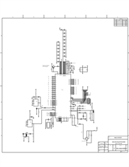
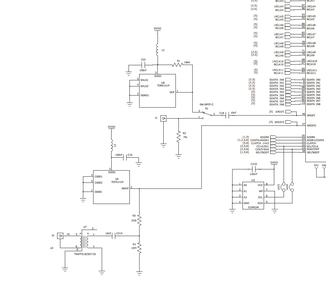
For item #2, Looking at the EVAL-ADAU1442 board we used a similar divider to drive the transformer. We used 243R and 107R.
For Item #3 and #4:
You will not need to boost it. The internal circuit will boost or limit as needed. The minimum of 0.2V means the RMS level of a "1" would be 0.2V. It will boost it internally to be properly decoded.
We designed the pin to adhere to the SPDIF standards so you would not need to add too much if any external circuitry. You can drive the optical parts directly and using a transformer for the transmit side I personally like. You will notice that the receive coaxial circuit in the EVAL-ADAU1442 eval board does not use a transformer but only a 75ohm line termination resistor. So this does open it up to ground loops.
So I did not do this design and I am not saying it is perfect. But, it does give you a basic idea of what you can do.
I will attach the eval board schematic:
Dave T
I totally understand, hope HighEnd Munich went well
1:
Thanks, thats great news, makes it even easier! I will defenitely use a transformer, already bought the pulse ones
2:
Thansks for the info!
3 and 4:
I will be using transformers on both the in and output coaxials. I will also add a optical input. I do not expect I can just input both the optical signal and the coax directly so I plan to add a Or gate and only use one signal at a time.
Good to hear that the input can handle both the raw optical and coax signals, makes my life easy :D
I will post a schematic ones I have it made if you don't mind doing a sanity check?
Cheers, Daniel
Hello Daniel,
The High End show went really well. Lots of customers stopped by our booth and we got some good feedback and made some new contacts.
DannerD3H said:
3 and 4:
I will be using transformers on both the in and output coaxials. I will also add a optical input. I do not expect I can just input both the optical signal and the coax directly so I plan to add a Or gate and only use one signal at a time.
You are correct that you cannot input and connect both of these at the same time. So either a mechanical switch or use a bi-lateral analog switch to select between them or of course a relay. An OR Gate will not work because it will not have an analog input, it will probably have a Schmidt trigger input.
Dave T
Good to hear! Sad I couldn't go.. Hope you will go next year!
Ah thanks for the input. Haven't dug to dee into that part yet.
Cheers
So this time I was the oine to get distracted..
BUT, Im back!
Would you mind doing a sanity check of this schematic DaveThib ?
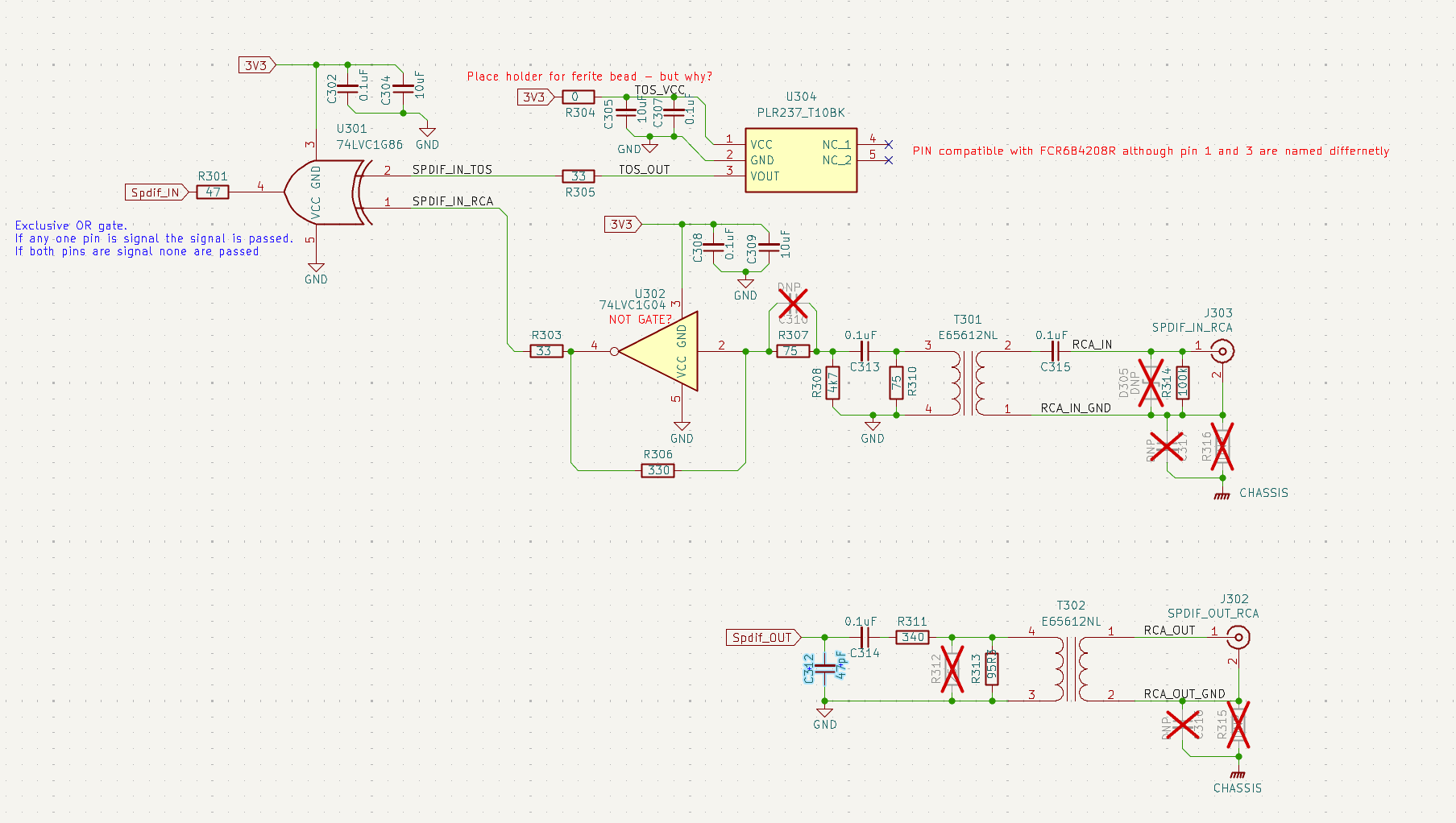
It is based mostly on the schematic of the "Freedsp Octavia" found in github (cannot share the link or the post will get banned). I know you said to avoid the or-gate, but he uses this specific device with succes and thus eleminate the need for any physical switches or anythin - Which i really like..
There is also a little bit of other designs in there regarding all the stuff between the Input RCA and the transformer. The RCA output is also not pressent at all in the octavia, so thats where I have the most doubts.
For specific questions I have the following:
Is the general approach okay for the ADAU14XX series?
Is the voltage devider at the output hitting acceptable levels?
What is the point of the multiple 0.1uF capacitors in line around the signal path. is it a DC block?
Best regards, Daniel
Hope all is well :)
Hello Daniel,
I think you need to be asking most of these questions to the transformer maker. They should have the recommended circuits for their transformer.
I do not know all the impedances involved. I do like that you do not tie the RCA in and out to any local ground. This will take advantage of having a transformer to isolate grounds between two devices.
The 0.1 caps are to keep DC out of the circuit and keep current from constantly flowing through the transformer windings even if there is no signal. The SPDIF signal is a signal where it is the change that is important not the actual level.
The Exclusive OR has me wondering?... I could go through the details but I just am not sure if this will work. I would also like to look at these signals on a scope to see where they sit when nothing is connected and when there is something connected but no active signal present? On the input side the secondary of the transformer will sit low due to the cap when there is no active signal. So then go through the inverter and the ExOR pin will be sitting high. This just seems like it will not work... But, I very much could be wrong here.
R306 looks wrong to me. A 330 ohm feedback resistor on an inverter? If I look at the feedback circuit with a DC analysis. You have 330 ohms in series with 75 ohms and a 4k7 ohms to ground. This means that the input pin of the inverter will be sitting high if the output is high. Well, if the output is high being fed back to the input then the input will be high and make the output go low. This is a strange circuit. This may only produce pulses or it might actually oscillate on its own.
Your second question about the gain is again, something for the transformer manufacturer. They will know the gain of the windings. They should have a recommended circuit for an SPDIF interface.
Sorry I am not being of much help here. If I were doing this here in my lab I would be breadboarding this for sure to actually see what is going on and if it works. I would do this well before making any PCBs.
Dave T
Hello again DaveThib !
Fair point that this isn't a topic for you/or ADI-EZs as it isn't strictly AnalogDevice related. But thanks for clearing it out regarding the ADAU!
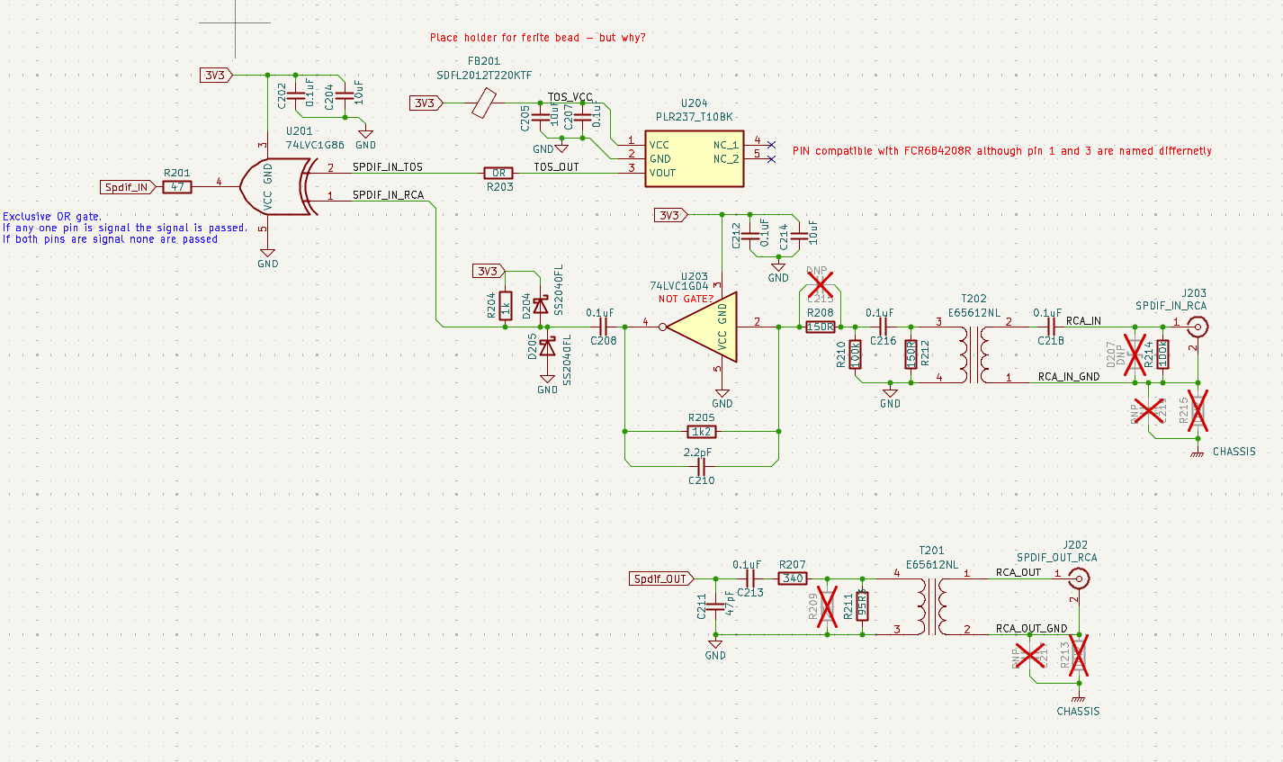
I realized that the schematic above was in fact outdated and unstable when nothing was connected to the coax - it would interubt the signal when using the optical line. Also this schematic does not allow both cables to be connected at the same time. So I think for now I will just siplify the design and use a relay/switch to change the input.
For the sake of comlpletion I will leave the updated schematic here:
The designer claims this works without issues, but only one cable may be connected at any one time.
I would prefer to have both cables connected and change input via a switch or through the DSP/uC.
Would you say the schematic from the eval is an okay start?
With that I mean:
a switch/relay to select the input connector.
No buffer between the coax and the ADAU
Output simply split for coax and optical?
I wil lcontinue to use transformers on both coax to create galvanic isolation.
You mentioned someoned from pulse contacted you. Do you have any idea whom/how I may contact Pulse? and do you think they will answer me for personal use?
Thanks once again Dave!
Cheers, Daniel
Please log in to reply.