PLL_CTRL0 editing should happen before PLL_ENABLE changes from 0 to 1, but sigmastudio generates code where PLL_CTRL0 is edited after PLL_ENABLE is changed from 0 to 1
Hello
We have a project utilizing the ADAU1462 and have noticed the file generation for the function "default_download_xx" where xx depends on the project name, might be wrong according to what is specified in the datasheet. I highlighted a statement in the datasheet below about the register PLL_CTRL0 saying:
"The value written to this register does not take effect until Register 0xF003 (PLL_ENABLE), Bit 0 (PLL_ENABLE) changes state from 0b0 to 0b1."
meanwhile the generated code from sigmastudio goes like this (i have snipped out irrelevant parts of the function for clarity):
PLL_ENABLE bit set to 0 on line 4
PLL_CTRL1 edited on line 5
PLL_ENABLE bit set to 1 on line 8
PLL_CTRL0 edited on line 12, after PLL_ENABLE changes from 0 to 1
This means the value of PLL_CTRL0 does not take effect, and the default value, in this case 96, is used. From my understanding this means there is no way to use non default value of PLL_CTRL0 register without either:
Manually editing the generated .h file moving line 12 up above line 8
Redo the PLL_ENABLE bit 0 to 1 sequence, which might require further manipulation of other registers to do correctly.
I have confirmed that 1. works, and have not looked much into 2.
What is the consequence of this? Any hardware setup that requires PLL_CTRL0 to be non default value will be using the default value anyways, making all clocking derrived from PLL_CTRL0 different from expected. This is especially a problem for the serial ports that derrive from the PLL clock.
When does PLL_CTRL0 use non default value? This is normally only the case when using a MCLK input that is not one of the following: 3.072MHz, 6.144MHz, 12.288MHz and 24.576MHz. Another case might be if you want to run the core at say half clock speed hoping to reduce the power consumption of the DSP hardware. I think most applications use these MCLK values, but there is also a huge list of alternative values in the datasheet table 20, which use different values as exaples.
I have confirmed this behavior in both sigmastudio rev4.7 and sigmastudio+ 2.3.0 by migrating the project, but same issue appears there aswell. The code example is from the migrated project.
void default_download_ADAU146XSCHEMATIC_0()
{
//...
SIGMA_WRITE_REGISTER_BLOCK(DEVICE_ADDR_ADAU146XSCHEMATIC_0, R8_PLL_ENABLE_ADDR_ADAU146XSCHEMATIC_0 , R8_PLL_ENABLE_SIZE_ADAU146XSCHEMATIC_0 , R8_PLL_ENABLE_ADAU146XSCHEMATIC_0_Data);
SIGMA_WRITE_REGISTER_BLOCK(DEVICE_ADDR_ADAU146XSCHEMATIC_0, R9_PLL_CTRL1_REGISTER_ADDR_ADAU146XSCHEMATIC_0 , R9_PLL_CTRL1_REGISTER_SIZE_ADAU146XSCHEMATIC_0 , R9_PLL_CTRL1_REGISTER_ADAU146XSCHEMATIC_0_Data);
SIGMA_WRITE_REGISTER_BLOCK(DEVICE_ADDR_ADAU146XSCHEMATIC_0, R10_PLL_CLK_SRC_REGISTER_ADDR_ADAU146XSCHEMATIC_0 , R10_PLL_CLK_SRC_REGISTER_SIZE_ADAU146XSCHEMATIC_0 , R10_PLL_CLK_SRC_REGISTER_ADAU146XSCHEMATIC_0_Data);
SIGMA_WRITE_REGISTER_BLOCK(DEVICE_ADDR_ADAU146XSCHEMATIC_0, R11_MCLK_OUT_REGISTER_ADDR_ADAU146XSCHEMATIC_0 , R11_MCLK_OUT_REGISTER_SIZE_ADAU146XSCHEMATIC_0 , R11_MCLK_OUT_REGISTER_ADAU146XSCHEMATIC_0_Data);
SIGMA_WRITE_REGISTER_BLOCK(DEVICE_ADDR_ADAU146XSCHEMATIC_0, R12_PLL_ENABLE_REGISTER_ADDR_ADAU146XSCHEMATIC_0 , R12_PLL_ENABLE_REGISTER_SIZE_ADAU146XSCHEMATIC_0 , R12_PLL_ENABLE_REGISTER_ADAU146XSCHEMATIC_0_Data);
SIGMA_WRITE_DELAY(DEVICE_ADDR_ADAU146XSCHEMATIC_0, R13_PLL_LOCK_DELAY_ADDR_ADAU146XSCHEMATIC_0 , R13_PLL_LOCK_DELAY_SIZE_ADAU146XSCHEMATIC_0 , R13_PLL_LOCK_DELAY_ADAU146XSCHEMATIC_0_Data);
SIGMA_WRITE_REGISTER_BLOCK(DEVICE_ADDR_ADAU146XSCHEMATIC_0, R14_POWER_ENABLE0_REGISTER_ADDR_ADAU146XSCHEMATIC_0 , R14_POWER_ENABLE0_REGISTER_SIZE_ADAU146XSCHEMATIC_0 , R14_POWER_ENABLE0_REGISTER_ADAU146XSCHEMATIC_0_Data);
SIGMA_WRITE_REGISTER_BLOCK(DEVICE_ADDR_ADAU146XSCHEMATIC_0, R15_POWER_ENABLE1_REGISTER_ADDR_ADAU146XSCHEMATIC_0 , R15_POWER_ENABLE1_REGISTER_SIZE_ADAU146XSCHEMATIC_0 , R15_POWER_ENABLE1_REGISTER_ADAU146XSCHEMATIC_0_Data);
SIGMA_WRITE_REGISTER_BLOCK(DEVICE_ADDR_ADAU146XSCHEMATIC_0, R16_PLL_CTRL0_ADDR_ADAU146XSCHEMATIC_0 , R16_PLL_CTRL0_SIZE_ADAU146XSCHEMATIC_0 , R16_PLL_CTRL0_ADAU146XSCHEMATIC_0_Data);
SIGMA_WRITE_REGISTER_BLOCK(DEVICE_ADDR_ADAU146XSCHEMATIC_0, R17_CLK_GEN1_M_ADDR_ADAU146XSCHEMATIC_0 , R17_CLK_GEN1_M_SIZE_ADAU146XSCHEMATIC_0 , R17_CLK_GEN1_M_ADAU146XSCHEMATIC_0_Data);
SIGMA_WRITE_REGISTER_BLOCK(DEVICE_ADDR_ADAU146XSCHEMATIC_0, R18_CLK_GEN2_M_ADDR_ADAU146XSCHEMATIC_0 , R18_CLK_GEN2_M_SIZE_ADAU146XSCHEMATIC_0 , R18_CLK_GEN2_M_ADAU146XSCHEMATIC_0_Data);
SIGMA_WRITE_REGISTER_BLOCK(DEVICE_ADDR_ADAU146XSCHEMATIC_0, R19_CLK_GEN3_M_ADDR_ADAU146XSCHEMATIC_0 , R19_CLK_GEN3_M_SIZE_ADAU146XSCHEMATIC_0 , R19_CLK_GEN3_M_ADAU146XSCHEMATIC_0_Data);
SIGMA_WRITE_REGISTER_BLOCK(DEVICE_ADDR_ADAU146XSCHEMATIC_0, R20_CLK_GEN3_N_ADDR_ADAU146XSCHEMATIC_0 , R20_CLK_GEN3_N_SIZE_ADAU146XSCHEMATIC_0 , R20_CLK_GEN3_N_ADAU146XSCHEMATIC_0_Data);
//...
}
To reproduce the issue:
create a project with the ADAU1462 DSP in sigmastudio or sigmastudio+
change the PLL feedback divider to anything but the default 96
make any schematic
compile the project and generate the output C files
observe that the xx.h file, where xx is the project name, contains the above mentioned order of edits to PLL_ENABLE, PLL_CTRL1 and PLL_CTRL0 registers
I am aware of this other issue 4 years ago about PLL_CTRL0. It is important for reproduciton of the problem to use a non default value of PLL_CTRL0. If the default value is used the the write to PLL_CTRL0 does not appear in the generated code files, and i think that is what this other issue has observed.
ADAU1466 sigmastudio 4.5.1 xx.h file problem : missing PLL_CTRL0 generation
Audio Signal Processors
SigmaStudio+ 2.3.0
software
Sigmastudio rev4.7
sigmaStudio 4.7
bug
SigmaDSP Audio Processors
adau1462
Show More
Hello NBL,
Sorry for the trouble caused.
I can see the problem here. I can see it in the capture window.
Like you mentioned in your issue reproduction steps,
NBL said:
create a project with the ADAU1462 DSP in sigmastudio or sigmastudio+
change the PLL feedback divider to anything but the default 96
make any schematic
If you compile, the 'changed PLL divider value' will not be reflected in the DSP, it is still 96 and the clock coming out is according to the default value 96. it needs a second Link compile download (without a reset or power cycle) for the changed PLL divider value to reflect in the DSP.
As you mentioned in your old thread, the ADAU1452 DLL works fine.
So, if you are using SS, you have to Link compile download twice for it to work as expected.
As you already figured out, if you are booting from a uC, then you can either manually change the order in the .h file (as you are doing now) or you can just copy those 5 commands from ADAU1452's exported files and paste it in your ADAU1467 exported code.
In your old thread regarding PLL_CTRL0 missing in generated file,
NBL said:
I am aware of this other issue 4 years ago about PLL_CTRL0. It is important for reproduciton of the problem to use a non default value of PLL_CTRL0. If the default value is used the the write to PLL_CTRL0 does not appear in the generated code files, and i think that is what this other issue has observed.
Yes, when you first compile (without touching the PLL_CTRL0 reg in SS), this PLL_CTRL0 is not included in the sequence (in capture window, exported files), when you make a change in the register (other than 96) and compile again, then this register is included in the sequence, but of course in the wrong order (after pll enable). This register is there for any further compilations but in the same wrong order.
This exists with sigma350 DLLs.
I know, I'm not saying anything new, you already figured this all out. Thanks for reporting this. I will pass the info to SS+ team.
Regards,
Harish
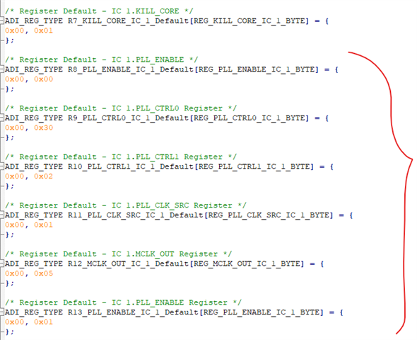
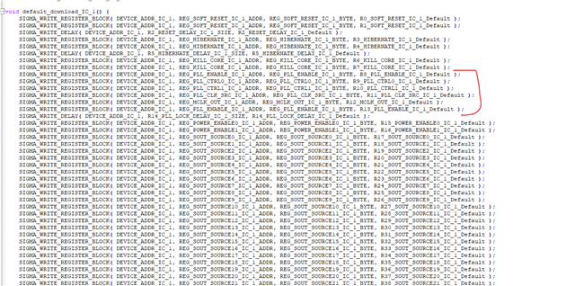
I hope it helps your team iron out the issue in future releases of SS
Regards
Nicklas
Please log in to reply.