ADAU1701 - Multiple I2S signals
Hi,
is it possible to input two I2S sources (same sampling frequency) into an ADAU1701 DSP and mix them to the final output?
Thanks in advance for any reply!
Audio Signal Processors
dsp
hardware
i2s
mixer
SigmaDSP Audio Processors
adau1701
Show More
Hello solonello,
Yes, you can connect up to four I2S inputs to the ADAU1701. Make sure that your serial clocks are synchronous to the two input sources (SDATA) and to the MCLK. Please refer page no 46 of the datasheet for more information on clocking and other configurations.
where is your MCLK coming from? Is it from the same domain where the I2S inputs are coming from?
This part doesn't have ASRCs, so your MCLK should be synchronous to the incoming clocks. If you apply clocks to the serial port and you do not have a master clock that is synchronous to this clock, then the converters will mute. please let us know if you need more info related to MCLK.
we have no idea about how you did your system clocking, so share us a block diagram of your system, then we will be able to suggest better solutions for your application.
and the basic schematic reference for your question is below.
This wiki page shows serial port routings and channel selections with ADAU1701, please go to the bottom of the page where you can find the routing info on sigma100 parts.
Regards,
Harish
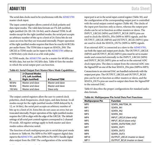
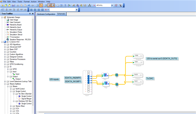
Hi Harishgowtham,
first of all thanks a lot for this so detailed reply.
In my project there is the need of a microcontroller, so I was thinking about setting the DSP as slave and have the MCU be the master and output the master clock. Do you think this could be a viable approach?
I could also set the DSP to be the master and have the master clock coming from a 12.288MHz crystal, I'm glad to receive suggestions about these two possibilities.
I would also like to ask another question, regarding the connections between the DSP and the amplifier. Since I'm using a digital amplifier, the DSP should also output the serial data (from the data sheet page you attached I see there are three serial output pins). My concerns are about the LRCK and BCLK to provide to the amplifier, should they come directly from the MCU (in the case it acts as master and the DSP as slave) or from the two pins MP10 and MP11 (according to the data sheet)? Or it is the same thing?
Sorry for the dumb question but, as you could imagine, I'm a newbie
Thanks again for any reply!
Hello solonello,
Harish and I work together to support the forum so I am going to jump in and respond to continue the conversation with less delay.
You are asking great questions and in some ways it is difficult to answer because there are so many ways to solve application problems and often there is no "right" way but just "different" ways. It is all about tradeoffs like space, costs, functional control, future plans, etc.
As Harish mentioned, the LRCLK and BCLK has to be divided down from the clock being fed to the MCLK input pin.
It might not be a good idea to have the MCU provide the MCLK because it can have a lot of jitter which can affect the audio performance. It might not be super important to your application, a desktop bluetooth speaker for background music certainly would not be critical to have the absolute best most stable MCLK. You would never hear the difference. The positive thing about having the MCU supply the MCLK is that there will be no crystal startup issues. It can be a problem.
What else needs a master clock in your system? Often the power amp ICs only need the LRCLK and BCLK. If nothing else needs MCLK then yes, just use a crystal on the ADAU1701 and set the ADAU1701 to be a clock master for the LRCLK and BCLK. This will be the simplest way to do it.
If something else needs the MCLK then it is a problem. The ADAU1701 does not have a CLK Out pin to send out the MCLK it derives from the crystal. You cannot, or should not, connect more than one device to a crystal. In this case I would use a clock oscillator module that has a built in crystal but outputs a CMOS level signal. You could send that to a couple of devices but if you need more then use a block buffer chip to derive several outputs from the same clock source. This is best for many reasons. But costs and space is a concern.
Regarding the connections to the amplifiers. Yes, MP10 and MP11 are the clock outputs and MP6 will be the data if you only need one stereo data line. I suggest going to MP7 if you need two more digital audio outputs. You can go to TDM4 format and use only MP6 but this starts to get more complicated and your bit clock frequency goes up. It is best to have the DSP be the clock master going to the amplifiers.
Will you need to send any audio data to the DSP from the MCU or any other part? You did not mention it. If you do need to bring in some audio then you will have to externally jumper the clock pins to the serial input port clock pins which are always a slave. So MP10 to MP4 and MP11 to MP5. This really should have been done internally but it was not. From a timing and external stray capacitance standpoint it actually is good to have to do this externally.
Are you using one of our power amps? We have some good ones we recently added to the portfolio. How much power and what is the load impedance and how many channels?
Dave T
Hi Dave!
Actually no other IC needs a master clock, the idea is having the MCU (ESP32-S3) receiving audio data via bluetooth or wifi, send it to the DSP via I2S in combination with some preconfigured audio effects (ideally on a different I2S channel, thus the original question of this thread) that the DSP should mix together, then have the DSP perform some other refinements, and finally output the final audio to the digital amplifier (I'm using the TAS5828M) that, as you stated correctly, does not need a master clock.
From your answer I see that is recommended and also simpler to have the master clock coming from a crystal.
There is one thing that is actually confusing me a bit:
"If you do need to bring in some audio then you will have to externally jumper the clock pins to the serial input port clock pins which are always a slave"
Yes(?), audio is sent from MCU to the DSP via I2S...should I jumper the pins you mentioned even in the case the DSP is master?
Thanks a lot for any reply, you're helping me a lot!
Hello solonello,
The MCU will need to be running at the same exact sampling rate as the DSP. So it will be best to have the DSP send the clocks to the MCU and have the MCU send the data. At least the LRCLK has to come from the DSP. Although, as I think about it, it might work out a little better to use the LRCLK to tell the MCU when the start of the frame is and then have it produce the bit clock that is in sync with the data. I have never tried this so I am not sure if it would work. The reason I am thinking of this is that I can see there being a problem with the delay of the data.
If the bit clock comes from the DSP then the MCU has to wait or have an interrupt to tell it a BCLK edge has happened. So it has to save the context, switch to an ISR and then pick up the next bit and send it to the pin to go to the DSP. That will probably take too much time. I do not know what hardware accelerators the ESP-32 has. If it has a serial port already then the MCU will not need to be involved. If that is the case then I suggest you first have the DSP send all the clocks to the MCU.
Do you have an oscilloscope? It would be handy to be looking at the clock and data at the same time. See how the timing is doing.
You have to jumper the pins on the DSP. There is no internal source for clocks on the serial input port. Only the serial output port has the ability to output clocks.
Dave T
Hi Dave,
at this point I think the only thing to do is to give it a try and see what happens. I'll set the DSP to act as master, with its own crystal, and send all the clocks to the MCU. The MCU will be sending the data to the DSP and DSP to the ampli.
I will also jumper the pins on the DSP as you suggested.
Unfortunately I do not have an oscilloscope.
Thanks again for the precious support, I'll update this thread with the results of my tests!
Please log in to reply.