TDM8 and Dante connections
Hi there,
I am developing a DSP board that accepts connections from Dante network audio cards. I have the Dante card set to provide 4 x TDM8 lines to create a 32 x 32 transmission line to the ADAU1467 DSP.
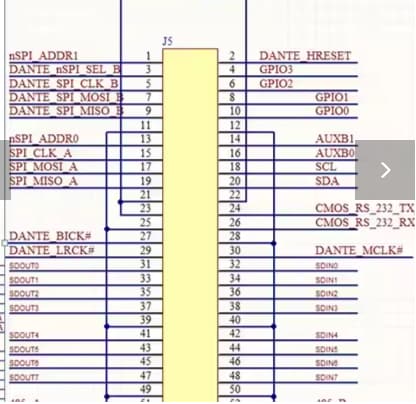
Normally, (on the Eval board for example), we run separate SCLK and LRCLK for each SDATA line to/from connected devices. The issue I am facing is that the Dante board (an Audiocom A203 adapter module) provides only a single MCLK, SCLK and LRCLK (see below image). I'm assuming that the Dante board will need to be set as a Master to work and my ADAU1467 will be a slave, therefore, how do I handle all of the SCLK and LRCLK pins on the ADAU1467? Do I need to buffer the SLKCK and LRCLK from the Dante board to each respective SCLK and LRCLK pin on the ADAU1467? Or do I only connect one set of SCLK and LRCLK on the ADAU1467?
Thanks for your advice and guidance!
Kind regards,
Mark
Audio Signal Processors
hardware
adau1467
AES67
Dante
SigmaDSP Audio Processors
Show More
Hello Mark,
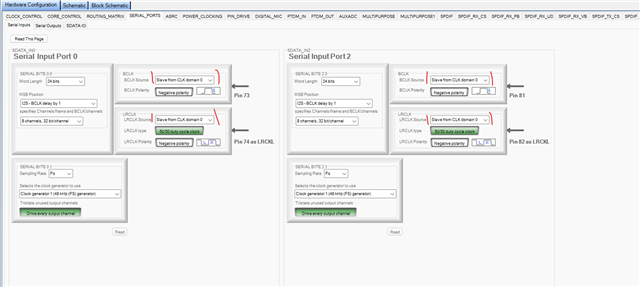
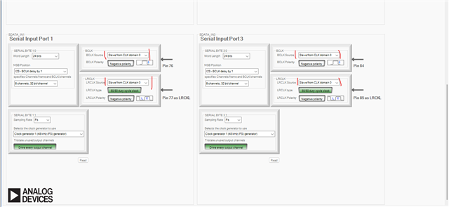
You can bring in one set of BCLK, LRCLK from Dante and connect it to any one of the serial input ports of the ADAU1467 and slave other input ports to this clock receiving port. Since you are using same sample rate and TDM8 format in all ports, it will be the same clock, so it can be shared internally.
Let's say you use serial input port 0 to receive clocks from Dante, all you have to do is to connect your BCLK, LRCLK from Dante to serial input port 0's BCLK, LRCLK respectively, then let the serial input ports 1,2,3 use port 0's clock internally and you can connect four data pins from Dante to four input ports respectively. Below is how the clocks are configured.
One important thing to note is that all you are talking about is the input side and you have not talked about the output side.
If you want to send out 4 TDM8 out of the DSP, then it's always recommended to set the DSP's serial ports as master, so that clock and data will be in same direction which will give you the best timing and signal integrity will be maintained. If your application can't allow that and you would have to set them as slave and use the same Dante clock as master in serial output side as well, then please note that you should have to connect your Dante clocks physically to any one of the serial output ports and let the other output ports use it, just like the input side. Note that clocks can't be shared between serial input and output ports. In this case, you can 'Y' the Dante clocks and send one pair to serial input 0, since the input domain gets its clock externally, other input ports can use it. And send another pair to serial out 0, since the output domain gets its clock externally, other output ports can use it.
Since the Dante is providing the MCLK to the DSP, I guess there won't be any other problem.
Note that since it's TDM8, you should be taking care of the signal integrity and PCB layout when you 'Y' the clocks.
I believe you are using either 48KHz or 96KHz sample rate, TDM8 at 192KHz is not supported unless the bit depth is 16 bits/channel. The max limit of serial ports is 24.576MHz (BCLK rate). So, 32bit/channel and TDM8 can be done only with 48KHz and 96KHz.
I hope this helps, feel free to reach out if you need any clarification.
Regards,
Harish
Hi Harish, thank you for your response, that is very helpful.
Apologies, I thought my "create a 32 x 32 transmission line" implied I want to send 4 x TDM8 back out after processing the signals. So yes, I need to consider sending back out.
Since the Dante connector only has a single BCLK and LRCLK, I guess I can't send the clocks from the ADAU1467 SDATA outputs anywhere, and therefore assume the Dante board will use the same clocks for the inputs and outputs. If I use a clock buffer on each and send them to the SDATA_IN0 and SDATA_OUT0 pins of the ADAU1467 (as per your example) will that be OK?
Do I need to use the MCLK from the Dante chip to the ADAU1467? Does this mean there is no need for the ASRCs for my data input and output?
Finally, I was hoping to use SDATAIO lines to add more TDM8 lines from the Dante board (i.e. up to 6 x TDM8 lines in and out), however I believe (if I'm reading the manual correctly) I can't use the spare 8 inputs of SDATA_IN0 for example to take a separate TDM8 input?! i.e. Does SDATA_IN0 have to be a TDM16 signal (even if only 8 channels used) if I want to supply another TDM8 to SDATAIO_0? Just wondering if there is a way to "fudge" it so I can get up to 48 channels in without needing a TDM16 input.
Many thanks,
Mark
Hello Mark,
MDThommo81 said:
Apologies, I thought my "create a 32 x 32 transmission line" implied I want to send 4 x TDM8 back out after processing the signals. So yes, I need to consider sending back out.
My bad, I overlooked the post. Thanks for clarification. I was about to tell you about using SDATAIOx pins.
MDThommo81 said:
Since the Dante connector only has a single BCLK and LRCLK, I guess I can't send the clocks from the ADAU1467 SDATA outputs anywhere, and therefore assume the Dante board will use the same clocks for the inputs and outputs. If I use a clock buffer on each and send them to the SDATA_IN0 and SDATA_OUT0 pins of the ADAU1467 (as per your example) will that be OK?
Yeah, it will be fine.
MDThommo81 said:
Do I need to use the MCLK from the Dante chip to the ADAU1467? Does this mean there is no need for the ASRCs for my data input and output?
Yes, if you are providing the MCLK and all other serial clocks to the DSP from Dante then it will all be in the same MCLK domain (serial clocks are derived from the same MCLK and core runs from the same MCLK too), so you will not need ASRC here.
MDThommo81 said:
Finally, I was hoping to use SDATAIO lines to add more TDM8 lines from the Dante board (i.e. up to 6 x TDM8 lines in and out), however I believe (if I'm reading the manual correctly) I can't use the spare 8 inputs of SDATA_IN0 for example to take a separate TDM8 input?! i.e. Does SDATA_IN0 have to be a TDM16 signal (even if only 8 channels used) if I want to supply another TDM8 to SDATAIO_0? Just wondering if there is a way to "fudge" it so I can get up to 48 channels in without needing a TDM16 input.
Actually, you can bring in 6 TDM8 into the core with the help of SDATAIO pins. You can use four primary pins for 4 TDM8 and two SDATAIO pins for 2 TDM8. Serial input port 0 and 1 have 16 channels, we use one primary pin to bring TDM8 and one SDATAIO pin for another TDM8 for serial port 0. The same goes for port 1. so now we have 32 channels input (4 TDM8).
we will use port 2 and 3's primary pins for 2 TDM8 respectively. So, it's 48 channels input (6 TDM8).
I have attached a project where I set up 48 channels input with 6 TDM8. I have configured the serial input port clocking page and SDATAIO pins. I have quickly tested here; I'm getting 48 channels input.
So, refer that project, I have also added comments, I hope you will configure the output side. Sorry that I only have time to create the input side and test it. The output side is pretty much the same.
48ch input with 6 TDM8 using SDATAIO pins.dspproj
Feel free to reach out if you need further assistance and let me know if I missed anything.
Regards,
Harish
Hi Harish, thank you so much for your detailed reply. This helps me learn a lot! Just one more question. If I were to reduce the number of Dante channels used in my project, and use another digital source that has its own master clock, how then can I integrate this new source into the project. To give a more clear example, 32 x 32 channels via Dante, and then 16 x 16 channels using a USB streamer. What does this mean for my project with regards to the MCLK?
Kind regards,
Mark
Hello Mark,
I guess now is the tricky part.
So, now I assume the Dante occupies 32 inputs slots of serial input port 0 and 1. each port has two TDM8 (one primary pin and one SDATAIO pin), so it will be 32 inputs with two ports. The same goes for the output port side. The serial input port 0 and 1 and output port 0 and 1 are slaves, Dante provides the serial clocks and MCLK to the DSP. That's all we already discussed above and it's alright.
So far, we have not used ASRC. Since the MCLK is synchronous (Dante and DSP MCLK's are in same domain)
Now, if you are bringing in the USB streamer which needs to be the serial clock master and also has its own MCLK, then we need ASRCs. But we only have 16 channel ASRCs in total for both input and output sides. So, 16 input and 16 output (16x16) for USB streamer is not possible.
So, if you increase the Dante channels to be 40 (5xTDM8) and reduce USB streamer channels to be 8 (1xTDM8), then we will try this by utilizing all 16 channel ASRCs.
8 ASRCs for the USB streamer's input and 8 ASRCs to USB streamer's output.
The reason for the ASRCs, as you know, the core gets its clocks from Dante and running, now if you introduce different sample rate clock (LRCLK) into the input port, there will be drifts between the DSP sample rate (Dante domain) and USB's LRCLK (USB streamer domain), which causes missing and repeating samples which will lead to clicks and pops and other distortion. using ASRCs will solve that.
The same happens in the output side, the core processes and put the data into the memory at DSP's sample rate (Dante domain) but since the serial output port is slaved to USB streamer, the serial out port runs at different rate than the DSP sample rate, so due to this drift, when serial out port picking up the data it either drops or repeats the sample, which leads to audio distortion. Using ASRC in the output side will solve this. This will be the case if you use TDM8 in and out with the USB streamer.
16x16 with USB streamer is just not possible since we would have no ASRCs left if we had used all 16 of them in the input side.
If you have an option like anyone of the input source (either Dante or USB) is active at a time, then we can set start pulse rate (DSP rate) to be respective serial input port's rate and switch it accordingly, this includes so much care and it should be done precisely, which leads to a different topic of discussion. if it's acceptable in your application, then we can discuss that in detail.
If you want all 48 channels (from two sources) to be active all the time, then what I have said above is the possible way.
Hope I have answered your question, if you still have questions, then feel free to reach out.
Regards,
Harish
Hi Harishgowtham , thank you for this excellent reply. It's a little tricky for me to follow, (not 100% sure on how the ASRCs are used as I've not used them before), but it makes sense at a high level for me.
I would only ever have Dante or USB active at one time, never at the same time. This is just about giving a user the option of using Dante or USB as an input source. So from what you alluded to suggests this may be possible... Can you help me understand this in more detail? Happy if you want to take this offline.
Dumb question, but again I've never had to do this, if I bring the MCLK from the Dante board (and/or USB streamer) how do I actually get it into my DSP and what settings do I need to make in SigmaStudio to make this happen. I currently have the EVAL-ADAU1452REVBZ and EVAL-ADAU1467Z (RevB) boards here that I'd like to test this out on. Perhaps just getting a single TDM8 line into SDATA_IN2 for example. Where do I feed the MCLK?
Thanks!
Mark
Hello Mark,
MDThommo81 said:
I would only ever have Dante or USB active at one time, never at the same time. This is just about giving a user the option of using Dante or USB as an input source. So from what you alluded to suggests this may be possible...
You will need to change the DSP start pulse setting to be either the Dante clocks or the Streamer clocks. If there is a switch on the front panel, then just send that to a GPIO and then the DSP can be programmed to change the Start Pulse register on its own. If you have a system controller, then it can do that. There are a few things to take care of here. I will get back to you about that.
MDThommo81 said:
Dumb question, but again I've never had to do this, if I bring the MCLK from the Dante board (and/or USB streamer) how do I actually get it into my DSP and what settings do I need to make in SigmaStudio to make this happen. I currently have the EVAL-ADAU1452REVBZ and EVAL-ADAU1467Z (RevB) boards here that I'd like to test this out on. Perhaps just getting a single TDM8 line into SDATA_IN2 for example. Where do I feed the MCLK?
I have answered this question in another post of yours few hours ago.
With ADAU1467Z, it can be done easily as I explained in that thread. But the ADAU1452 eval board, there are no resistors in the path to remove and give the clocks.
thanks Harish! I have the ADAU1467 eval' board too, so maybe I'll try it on that one today and let you know. But knowing this is possible is a great start. It means that I can allow for this functionality as I design my own DSP board to accommodate this functionality. If there are any specifics I need to consider in the circuit design for this (that doesn't appear on the evaluation board) then it would be great to be aware of those things, thank you!
Kind regards,
Mark
Please log in to reply.