ADAU1452 and CS42448 PARTIALLY WORKING
Hello everyone,
After playing around for a while with what seems to be a familiar devkit in the forum
(based in 2 PCB, one for the ADAU1452 DSP and a daughter board with the CS42448 CODEC)
I managed to get the 6 input channels working, and 4 out of 8 output channels also properly working.
The devkit I'm talking about, can also be found in this forum post:
RE: ADAU1452 + CODEC CS42448 is not working
So I should be sharing the same hardware configuration.
The project I'm using can be found below:
audio_system.dspproj
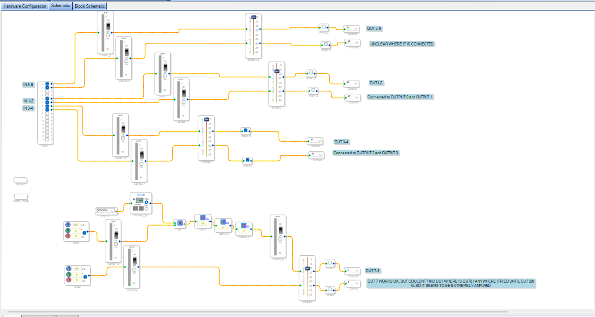
I also attach a picture of the schematic:
(please note the ports on the outputs don't match exactly the ones being used, as I have played around changing them many times)
So the issue is as follows:
As marked in the CODEC board:
- Inputs 1 to 6 work properly.
- Outputs 1 to 4 work also properly (or seem to do so).
- Outputs 5 to 8 DON'T
The failing outputs still seem to deliver some output, but not as I would expect, and here are the details I could notice about it:
- The outputs are completely distorted.
- They seem to have clipping, as they were absurdly highly amplified.
- Muting those outputs works correctly.
- Using a volume widget right before the connection to the outputs seems to have absolutely no effect.
- When unmuted, and nothing connected to the inputs routed to those outputs, there is fairly loud white noise coming out.
- When unmuted, and audio connected to the inputs routed to thouse outputs, the audio in the output is incredibly distorted, but sort of recognizable though.
- When using an internally generated tone, the signal gets distorted as previosly mentioned.
My guess is there may be some issues with my register controls, but unfortunately I'm not experienced enough to understand how to set them up properly.
I got told I need to use TDM8 and 192KHz, but I am not very familiar with this kind of configurations. (I may be using I2S instead without knowing it).
Could anyone help with this?
Thank you very much in advance for your support.
Audio Signal Processors
adau1452
software
cs42448
sigmaStudio 4.7
adau1452 sigmastudio
SigmaDSP Audio Processors
Show More
Hello ,
I can see that it's SPORT config and connection issue between the DSP and CODEC. you have chosen channels randomly which led to this.
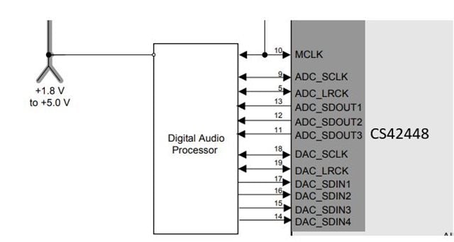
I had a look at the CS2448 datasheet, I noticed that it features three ADC data output lines and four DAC data input lines. Based on this, the DSP and codec should ideally be connected as shown in the block diagram below:
The ADAU1452 has four serial input port and output ports. thus, four data input pins (SDATA_IN0 to SDATA_IN3) and four output data pins (SDATA_OUT0 to SDATA_OUT3). Each of these pins can handle 2, 4, or 8 channels, and some pins are capable of handling up to 16 channels (SDATA_IN0/1 and SDATA_OUT0/1).
Regarding the operating mode:
In I²S Mode:
Since you are using I²S mode for 6 input channels and 8 output channels, you should utilize three input SPORTs and four output SPORTs.
You can find further details about this configuration in the datasheet ADAU1452/ADAU1451/ADAU1450 (Rev.D)
In the project you shared, only SPORT0 is configured for input and set in I²S mode, which is why you are receiving only channels 0 and 1.
To handle 6 input channels, you will need to configure two additional SPORTs for input. I configured input SPORT 1 and 2 along with existing SPORT 0.
If I have to go in detail, you should connect ADC_SDOUT1 to SDATA_IN0, ADC_SDOUT2 to SDATA_IN1, ADC_SDOUT3 to SDATA_IN2.
In your project, you set the DSP as master serial clock master, so set all serial input ports as master and just connect input port 0 clocks to ADC clocks, i.e. connect BCLK_IN0 and LRCLK_IN0 to ADC_SCLK and ADC_LRCLK respectively.
The same with the DAC_SDINx to SDATA_OUTx pins and clocks.
I have attached a passthrough project that supports 6 ADC inputs and 8 DAC outputs below.
In TDM Mode:
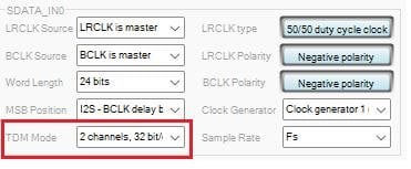
It is also possible to use a single SPORT for all 6 ADC inputs and 8 DAC outputs by switching to TDM8 mode.
If you choose this method, please ensure that both the codec's register settings and the ADAU1452 SPORT configurations are set for TDM operation, according to the datasheet.
Let me know if you have any questions or if you need help with the TDM passthrough project setup.
I2s_ 6_ADC_8DAC_passthrough.dspproj
Hope this helps!
Regards,
Harish
Hi again,
In regards to the communication mode, even though my configuration was in I2S, it seems the CS42448 was expecting TDM.
(it is the default as far as I understood, and to make sure, today I plugged a uC on the I2C bus an read all internal registers).
And probably that's why there were 4 channels working (1-2, and 3-4).
So for now it would be better to stick to the TDM8 mode also for the test project,
and when I get to know better how it works with its advantages and disadvantages
I will decide either to stick to it or move to I2S (changing also the config of the CS42448).
Harishgowtham Could you please provide a project with the right configuration for the TDM8 ?
Thanks!
P.D. Attached you can find the values of all registers read from CS42448 just in case they're of any value
(even though some register names may be wrong, the values are right)
Fullscreen
cs42448_regs.txt
Download
Reading CS42448 registers (0x01 to 0x1B):
Register 0x01 (Chip ID & Revision): 0x04
Bit 7: 0 - Chip ID Bit 3
Bit 6: 0 - Chip ID Bit 2
Bit 5: 0 - Chip ID Bit 1
Bit 4: 0 - Chip ID Bit 0
Bit 3: 0 - Revision ID Bit 3
Bit 2: 1 - Revision ID Bit 2
Bit 1: 0 - Revision ID Bit 1
Bit 0: 0 - Revision ID Bit 0
Register 0x02 (Power Control): 0x00
Bit 7: 0 - PDN_ADC3
Bit 6: 0 - PDN_ADC2
Bit 5: 0 - PDN_ADC1
Bit 4: 0 - PDN_DAC4
Bit 3: 0 - PDN_DAC3
Bit 2: 0 - PDN_DAC2
Bit 1: 0 - PDN_DAC1
Bit 0: 0 - PDN
Register 0x03 (Functional Mode): 0xF0
Bit 7: 1 - DAC_FM1
Bit 6: 1 - DAC_FM0
Bit 5: 1 - ADC_FM1
Bit 4: 1 - ADC_FM0
Bit 3: 0 - Reserved
Bit 2: 0 - Reserved
Bit 1: 0 - Reserved
Bit 0: 0 - Reserved
Register 0x04 (Interface Formats): 0x36
Bit 7: 0 - DAC_DIF2
Bit 6: 0 - DAC_DIF1
Bit 5: 1 - DAC_DIF0
Bit 4: 1 - ADC_DIF2
Bit 3: 0 - ADC_DIF1
Bit 2: 1 - ADC_DIF0
Bit 1: 1 - Reserved
Bit 0: 0 - Reserved
Register 0x05 (ADC Control & DAC De-Emphasis): 0x00
Bit 7: 0 - ADC1-2_HPF_FREEZE
Bit 6: 0 - ADC3_HPF_FREEZE
Bit 5: 0 - DAC_DEM
Bit 4: 0 - ADC1_SINGLE
Bit 3: 0 - ADC2_SINGLE
Bit 2: 0 - ADC3_SINGLE
Bit 1: 0 - AIN5_MUX
Bit 0: 0 - AIN6_MUX
Register 0x06 (Transition Control): 0x10
Bit 7: 0 - DAC_SZC1
Bit 6: 0 - DAC_SZC0
Bit 5: 0 - ADC_SZC1
Bit 4: 1 - ADC_SZC0
Bit 3: 0 - Reserved
Bit 2: 0 - Reserved
Bit 1: 0 - Reserved
Bit 0: 0 - Reserved
Register 0x07 (DAC Channel Mute): 0x00
Bit 7: 0 - AOUT8_MUTE
Bit 6: 0 - AOUT7_MUTE
Bit 5: 0 - AOUT6_MUTE
Bit 4: 0 - AOUT5_MUTE
Bit 3: 0 - AOUT4_MUTE
Bit 2: 0 - AOUT3_MUTE
Bit 1: 0 - AOUT2_MUTE
Bit 0: 0 - AOUT1_MUTE
Register 0x08 (Volume Control 1): 0x00
Bit 7: 0 - AOUT1_VOL7
Bit 6: 0 - AOUT1_VOL6
Bit 5: 0 - AOUT1_VOL5
Bit 4: 0 - AOUT1_VOL4
Bit 3: 0 - AOUT1_VOL3
Bit 2: 0 - AOUT1_VOL2
Bit 1: 0 - AOUT1_VOL1
Bit 0: 0 - AOUT1_VOL0
Register 0x09 (Volume Control 2): 0x00
Bit 7: 0 - AOUT2_VOL7
Bit 6: 0 - AOUT2_VOL6
Bit 5: 0 - AOUT2_VOL5
Bit 4: 0 - AOUT2_VOL4
Bit 3: 0 - AOUT2_VOL3
Bit 2: 0 - AOUT2_VOL2
Bit 1: 0 - AOUT2_VOL1
Bit 0: 0 - AOUT2_VOL0
Register 0x0A (Volume Control 3): 0x00
Bit 7: 0 - AOUT3_VOL7
Bit 6: 0 - AOUT3_VOL6
Bit 5: 0 - AOUT3_VOL5
Bit 4: 0 - AOUT3_VOL4
Bit 3: 0 - AOUT3_VOL3
Bit 2: 0 - AOUT3_VOL2
Bit 1: 0 - AOUT3_VOL1
Bit 0: 0 - AOUT3_VOL0
Register 0x0B (Volume Control 4): 0x00
Bit 7: 0 - AOUT4_VOL7
Bit 6: 0 - AOUT4_VOL6
Bit 5: 0 - AOUT4_VOL5
Bit 4: 0 - AOUT4_VOL4
Bit 3: 0 - AOUT4_VOL3
Bit 2: 0 - AOUT4_VOL2
Bit 1: 0 - AOUT4_VOL1
Bit 0: 0 - AOUT4_VOL0
Register 0x0C (Volume Control 5): 0x00
Bit 7: 0 - AOUT5_VOL7
Bit 6: 0 - AOUT5_VOL6
Bit 5: 0 - AOUT5_VOL5
Bit 4: 0 - AOUT5_VOL4
Bit 3: 0 - AOUT5_VOL3
Bit 2: 0 - AOUT5_VOL2
Bit 1: 0 - AOUT5_VOL1
Bit 0: 0 - AOUT5_VOL0
Register 0x0D (Volume Control 6): 0x00
Bit 7: 0 - AOUT6_VOL7
Bit 6: 0 - AOUT6_VOL6
Bit 5: 0 - AOUT6_VOL5
Bit 4: 0 - AOUT6_VOL4
Bit 3: 0 - AOUT6_VOL3
Bit 2: 0 - AOUT6_VOL2
Bit 1: 0 - AOUT6_VOL1
Bit 0: 0 - AOUT6_VOL0
Register 0x0E (Volume Control 7): 0x00
Bit 7: 0 - AOUT7_VOL7
Bit 6: 0 - AOUT7_VOL6
Bit 5: 0 - AOUT7_VOL5
Bit 4: 0 - AOUT7_VOL4
Bit 3: 0 - AOUT7_VOL3
Bit 2: 0 - AOUT7_VOL2
Bit 1: 0 - AOUT7_VOL1
Bit 0: 0 - AOUT7_VOL0
Register 0x0F (Volume Control 8): 0x00
Bit 7: 0 - AOUT8_VOL7
Bit 6: 0 - AOUT8_VOL6
Bit 5: 0 - AOUT8_VOL5
Bit 4: 0 - AOUT8_VOL4
Bit 3: 0 - AOUT8_VOL3
Bit 2: 0 - AOUT8_VOL2
Bit 1: 0 - AOUT8_VOL1
Bit 0: 0 - AOUT8_VOL0
Register 0x10 (Beep Frequency & Timing): 0x00
Bit 7: 0 - INV_AOUT8
Bit 6: 0 - INV_AOUT7
Bit 5: 0 - INV_AOUT6
Bit 4: 0 - INV_AOUT5
Bit 3: 0 - INV_AOUT4
Bit 2: 0 - INV_AOUT3
Bit 1: 0 - INV_AOUT2
Bit 0: 0 - INV_AOUT1
Register 0x11 (Beep Volume & On Time): 0x00
Bit 7: 0 - AIN1_VOL7
Bit 6: 0 - AIN1_VOL6
Bit 5: 0 - AIN1_VOL5
Bit 4: 0 - AIN1_VOL4
Bit 3: 0 - AIN1_VOL3
Bit 2: 0 - AIN1_VOL2
Bit 1: 0 - AIN1_VOL1
Bit 0: 0 - AIN1_VOL0
Register 0x12 (Beep Off Time & Repeat Count): 0x00
Bit 7: 0 - AIN2_VOL7
Bit 6: 0 - AIN2_VOL6
Bit 5: 0 - AIN2_VOL5
Bit 4: 0 - AIN2_VOL4
Bit 3: 0 - AIN2_VOL3
Bit 2: 0 - AIN2_VOL2
Bit 1: 0 - AIN2_VOL1
Bit 0: 0 - AIN2_VOL0
Register 0x13 (Beep Tone Configuration): 0x00
Bit 7: 0 - AIN3_VOL7
Bit 6: 0 - AIN3_VOL6
Bit 5: 0 - AIN3_VOL5
Bit 4: 0 - AIN3_VOL4
Bit 3: 0 - AIN3_VOL3
Bit 2: 0 - AIN3_VOL2
Bit 1: 0 - AIN3_VOL1
Bit 0: 0 - AIN3_VOL0
Register 0x14 (Beep & Tone Control): 0x00
Bit 7: 0 - AIN4_VOL7
Bit 6: 0 - AIN4_VOL6
Bit 5: 0 - AIN4_VOL5
Bit 4: 0 - AIN4_VOL4
Bit 3: 0 - AIN4_VOL3
Bit 2: 0 - AIN4_VOL2
Bit 1: 0 - AIN4_VOL1
Bit 0: 0 - AIN4_VOL0
Register 0x15 (Beep & Tone Volume): 0x00
Bit 7: 0 - AIN5_VOL7
Bit 6: 0 - AIN5_VOL6
Bit 5: 0 - AIN5_VOL5
Bit 4: 0 - AIN5_VOL4
Bit 3: 0 - AIN5_VOL3
Bit 2: 0 - AIN5_VOL2
Bit 1: 0 - AIN5_VOL1
Bit 0: 0 - AIN5_VOL0
Register 0x16 (Beep & Tone Frequency): 0x00
Bit 7: 0 - AIN6_VOL7
Bit 6: 0 - AIN6_VOL6
Bit 5: 0 - AIN6_VOL5
Bit 4: 0 - AIN6_VOL4
Bit 3: 0 - AIN6_VOL3
Bit 2: 0 - AIN6_VOL2
Bit 1: 0 - AIN6_VOL1
Bit 0: 0 - AIN6_VOL0
Register 0x17 (Beep & Tone On Time): 0x00
Bit 7: 0 - INV_AIN6
Bit 6: 0 - INV_AIN5
Bit 5: 0 - INV_AIN4
Bit 4: 0 - INV_AIN3
Bit 3: 0 - INV_AIN2
Bit 2: 0 - INV_AIN1
Bit 1: 0 - Reserved
Bit 0: 0 - Reserved
Register 0x18 (Status Control): 0x00
Bit 7: 0 - UNLOCK
Bit 6: 0 - ADC_OVFL
Bit 5: 0 - DAC_OVFL
Bit 4: 0 - ADC_CLIP
Bit 3: 0 - Reserved
Bit 2: 0 - Reserved
Bit 1: 0 - Reserved
Bit 0: 0 - Reserved
Register 0x19 (Status): 0x00
Bit 7: 0 - UNLOCK
Bit 6: 0 - ADC_OVFL
Bit 5: 0 - DAC_OVFL
Bit 4: 0 - ADC_CLIP
Bit 3: 0 - Reserved
Bit 2: 0 - Reserved
Bit 1: 0 - Reserved
Bit 0: 0 - Reserved
Register 0x1A (Status Mask): 0x00
Bit 7: 0 - UNLOCK_MASK
Bit 6: 0 - ADC_OVFL_MASK
Bit 5: 0 - DAC_OVFL_MASK
Bit 4: 0 - ADC_CLIP_MASK
Bit 3: 0 - Reserved
Bit 2: 0 - Reserved
Bit 1: 0 - Reserved
Bit 0: 0 - Reserved
Register 0x1B (MUTEC Control): 0x00
Bit 7: 0 - MUTEC_POL
Bit 6: 0 - MUTEC_CTRL
Bit 5: 0 - MUTEC_SEL2
Bit 4: 0 - MUTEC_SEL1
Bit 3: 0 - MUTEC_SEL0
Bit 2: 0 - Reserved
Bit 1: 0 - Reserved
Bit 0: 0 - Reserved
Hello,
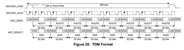
Your codec does support TDM8, and the frame clock is in pulse mode and the bit clock (BCLK) is set to 256×fs = 12.288 MHz. Based on this configuration, I’ve created a TDM8 audio passthrough project in Sigma Studio. please find the project below.
Below is a timing diagram from your codec's datasheet.
Default Interface Format Register Configuration
Register 0x04 (Interface Formats): 0x36
Bit 7: 0 - FREEZE
Bit 6: 0 - AUX_DIF
Bit 5: 1 - DAC_DIF2 //TDM Mode,24bit(slave only)
Bit 4: 1 - DAC_DIF1
Bit 3: 0 - DAC_DIF0
Bit 2: 1 - ADC_DIF2 //TDM Mode,24bit(slave only)
Bit 1: 1 - ADC_DIF1
Bit 0: 0 - ADC_DIF0
audio passthrough_TDM 8.dspproj
Regards,
Harish
Hi harish,
I have tried the passhrough project you've created, and it doesn't work as expected.
It seems there may be an offset in somewhere I can't figure out (made some modifications to the clocks, but didn't get it better).
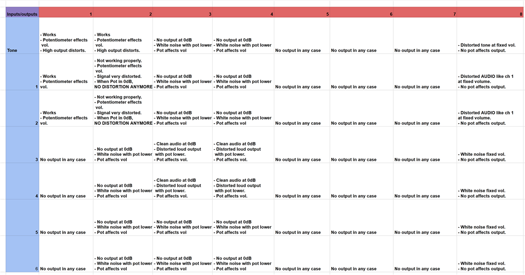
Here a table with the current results between inputs and outputs
Could you by chance identify the issue based on the output behaviour?
Thanks!
Cheers!
Hi again
Harishgowtham
Any news in regards to the topic?
I still didn't figure out how to make it work.
Kind regards
Hello raulsphaira,
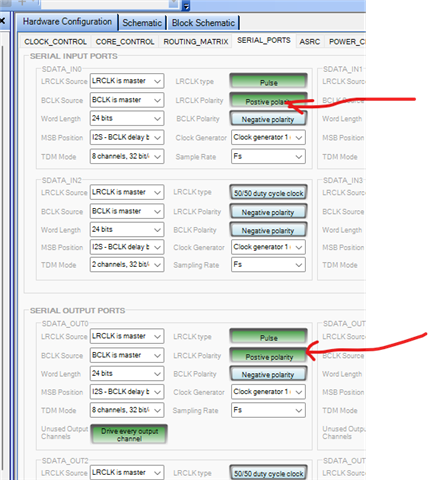
Try changing the LRCLK polarity to positive. The clocking diagram shows the pulse mode with the pulse rising at the start of the frame.
This would cause the sign bit to be missed and so that would make a mess of level and lots of distortion.
Dave T
Thank you so much!
Finally it seems at least the basic passthrough example is working.
audio passthrough_TDM_8_tones.dspproj
So as it seems there may be other people having a similar problem with this driver, here I post the basic project which worked for me
(and should work with everyone else having the chinese CS42448 codec board) for others to test.
Besides the the passthrough, I've added tones for each of the outputs, so it can be tested even without input.
Thank you again.
Cheers!
YAY!!!! An internal oscillator for testing only part of the signal path to simplify things!! Well done!!
Have you watched my troubleshooting video on the YouTube channel?
Dave T
Hi Dave, and thank you again
I am subscribed to your channel @HowtoSigmaDSP and have checked some of your videos, and they were pretty useful actually!
But as I am not using an official devboard, and had also some problems with the CS42448 codec itself, I couldn't follow all of them .
Probably now I can go further with some, will check.
Cheers!
Please log in to reply.