Help with configuring adau1450 registers using I2C
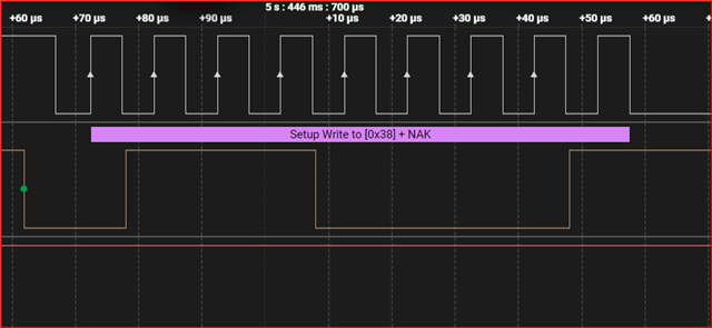
I want to use the STM32 microcontroller to configure the ADAU1450 DSP registers using I2C. I have tried to follow the steps for configuring this DSP registers as explained in Table 27 of the ADAU1450/1452 datasheet, but I am not getting any response from the ADAU1450. I don't know where I could be going wrong.
here are my header and source files...
#ifndef I2C_H_
#define I2C_H_
#include "stm32.h"
#include <stdint.h>
void I2C1_Init(void);
void I2C1_Write(uint8_t saddr, uint16_t reg, const uint8_t *data, uint16_t len);
void I2C1_Read(uint8_t saddr, uint16_t reg, uint8_t *data, uint16_t len);
#include "i2c.h"
#define I2C_SPEED 40 // ~100kHz for 8 MHz APB1
#define I2C_TRISE 9
#define I2C1_EN (1U << 21)
#define GPIOB_EN (1U << 3)
void I2C1_Init(void)
{
RCC->APB2ENR |= GPIOB_EN;
RCC->APB1ENR |= I2C1_EN;
// PB6, PB7 Alternate function open-drain
GPIOB->CRL &= ~((0xF << 24) | (0xF << 28));
GPIOB->CRL |= ((0xB << 24) | (0xB << 28)); // MODE=11 (50MHz), CNF=10 (AF open-drain)
// Software reset
I2C1->CR1 |= (1 << 15);
I2C1->CR1 &= ~(1 << 15);
I2C1->CR2 = 8; // APB1 = 8 MHz
I2C1->CCR = I2C_SPEED;
I2C1->TRISE = I2C_TRISE;
I2C1->CR1 |= (1 << 0); // Enable I2C1
}
void I2C1_Write(uint8_t saddr, uint16_t reg, const uint8_t *data, uint16_t len)
{
volatile int tmp;
while (I2C1->SR2 & (1 << 1)); // Wait if busy
I2C1->CR1 |= (1 << 8); // START
while (!(I2C1->SR1 & (1 << 0))); // SB
I2C1->DR = saddr << 1; // Write address
while (!(I2C1->SR1 & (1 << 1))); // ADDR
tmp = I2C1->SR2;
// Send 16-bit register address
while (!(I2C1->SR1 & (1 << 7)));
I2C1->DR = (reg >> 8) & 0xFF;
while (!(I2C1->SR1 & (1 << 7)));
I2C1->DR = reg & 0xFF;
// Send data
for (uint16_t i = 0; i < len; i++)
{
while (!(I2C1->SR1 & (1 << 7)));
I2C1->DR = data[i];
}
while (!(I2C1->SR1 & (1 << 2))); // BTF
I2C1->CR1 |= (1 << 9); // STOP
}
void I2C1_Read(uint8_t saddr, uint16_t reg, uint8_t *data, uint16_t len)
{
volatile int tmp;
while (I2C1->SR2 & (1 << 1)); // Busy
I2C1->CR1 |= (1 << 8); // START
while (!(I2C1->SR1 & (1 << 0)));
I2C1->DR = saddr << 1; // Write mode
while (!(I2C1->SR1 & (1 << 1)));
tmp = I2C1->SR2;
while (!(I2C1->SR1 & (1 << 7)));
I2C1->DR = (reg >> 8) & 0xFF;
while (!(I2C1->SR1 & (1 << 7)));
I2C1->DR = reg & 0xFF;
while (!(I2C1->SR1 & (1 << 7)));
I2C1->CR1 |= (1 << 8); // Re-START
while (!(I2C1->SR1 & (1 << 0)));
I2C1->DR = (saddr << 1) | 1; // Read mode
while (!(I2C1->SR1 & (1 << 1)));
tmp = I2C1->SR2;
if (len == 1)
{
I2C1->CR1 &= ~(1 << 10); // ACK = 0
I2C1->CR1 |= (1 << 9); // STOP
while (!(I2C1->SR1 & (1 << 6)));
data[0] = I2C1->DR;
}
else
{
I2C1->CR1 |= (1 << 10); // ACK
for (uint16_t i = 0; i < len; i++)
{
if (i == len - 2)
I2C1->CR1 &= ~(1 << 10); // NACK before last byte
if (i == len - 1)
I2C1->CR1 |= (1 << 9); // STOP
while (!(I2C1->SR1 & (1 << 6)));
data[i] = I2C1->DR;
}
}
}
#ifndef ADAU1450_H_
#define ADAU1450_H_
#include <stdint.h>
#define ADAU1450_I2C_ADDR 0x38 // Make sure ADDR0 and ADDR1 = 0
#define PLL_CTRL0 0xF000
#define PLL_CTRL1 0xF001
#define PLL_CLK_SRC 0xF002
#define PLL_ENABLE 0xF003
#define PLL_LOCK 0xF004
#define MCLK_OUT_ENABLE 0xF005
#define SOFT_RESET 0xF890
#define HIBERNATE 0xF400
#define KILL_CORE 0xF403
#define START_CORE 0xF402
#define SYS_PWR 0xF050
#define SYS_DISABLE 0xF051
void adau1450_init(void);
void adau1450_write(uint16_t reg, uint8_t val);
uint8_t adau1450_read(uint16_t reg);
uint8_t adau1450_check_pll_lock(void);
#include "i2c.h"
#include "adau1450.h"
int main(void)
{
I2C1_Init();
adau1450_init();
uint8_t pll_val;
while (1)
{
pll_val = adau1450_read(PLL_CTRL0);
for (volatile int i = 0; i < 100000; i++);
}
}
And finnally, here is the screenshot of what I am getting on logic analyzer...
Audio Signal Processors
adau1452
software
microcontroller
embedded c
adau1450
SigmaDSP Audio Processors
SigmaDSP
Show More
Hello FELM,
It will take some time to look at your code.
so why don't you try with the code given in the wiki page. It's a tested code and is working for a long time. It's written for teensy (arduino based), so you would have to change a very minimal part of the code.
Just compile your project in sigma studio and export the system files and integrate it with the wiki code.
Interfacing SigmaDSP Processors with a Microcontroller [Analog Devices Wiki]
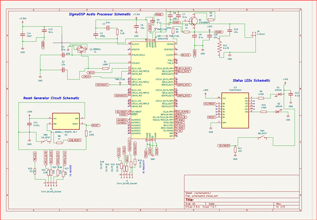
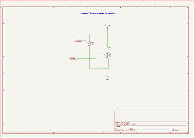
Also attach your hardware schematics too, hope you have a pull up resistors on the I2C line.
Regards,
Harish
Noted, let me go through it.
The schematics. And yes, I added the pull up resistors...


Please log in to reply.