Issues with serial input ports
Hi all,
I'm having trouble getting the serial input ports other than the first one to work.
This is my setup:
Serial input port 0: it's connected to an ADC that acts as an I2S master.
Serial input port 1: it's connected to a microcontroller that acts as an I2S master.
In SigmaStudio I configured the serial ports like this:
Serial input port 0: LRCLK: slave from clock domain 0; BCLK: slave from clock domain 0
Serial input port 1: LRCLK: slave from clock domain 1; BCLK: slave from clock domain 1
I use channels 0/1 as inputs from serial port 0, and 16/17 as input from serial port 1.
The ADC communicates without problems on serial port 0, while on serial port 1 I have no input from the microcontroller.
However, by connecting the microcontroller to serial port 0, the audio can be heard without problems.
The same problem also occurs on serial port 2 and 3, so the only one that seems to work is the serial port 0.
I'm attaching the project in case it's of interest to you.
Thanks in advance for any help!
1346.ADAU1452.dspproj
Audio Signal Processors
adau1452
adc
hardware
mcu
serial input
i2s
SigmaDSP Audio Processors
Show More
Hello solonello,
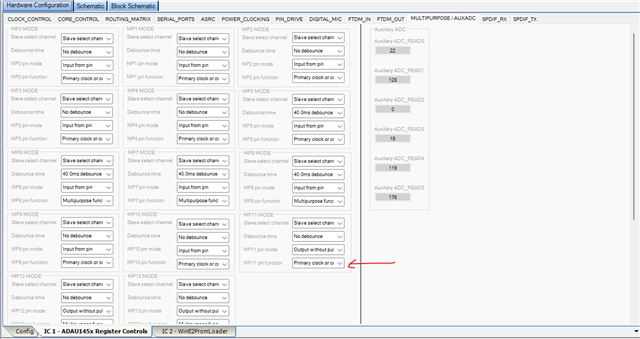
You set the MP11 as a multipurpose pin, MP is muxed with LRCLK_IN1.
The primary function is LRCLK. Set it to 'primary function', you will be able to get the output.
The same goes for LRCLK_IN2/MP12 and LRCLK_IN3/MP13. Set them to 'primary function'.
Another little detail is that, since you run the port as slave, you will have to set the pin as 'primary pin'.
If the LRCLK is master, even you set it as GPIO, the data will be clocking out. It can be useful in some situations. I will explain it when it's required, I don't want to overwhelm the response.
One more thing is, Since the serial port 0 and 1 are slave to external clocks, you may need to use ASRCs. I can see you are using CG1 as your sample rate (start pulse) source.
I don't know about where your MCLK is coming from, if your DSP, ADC and MCU all are running in a same MCLK domain, then no need for ASRCs.
If MCLK to the DSP is from crystal, then you have to use 2 ASRCs, each for a serial port. The attached modified project is configured for it. (I changed the slave port to SPI, please change that back to I2C as you already set)
If the MCLK to the DSP is coming from MCU, then you will have to use ASRC only for ADC input (serial port 0)
If the DSP and ADC are in same MCLK domain but MCU runs on its own MCLK, them MCU input (serial port 1) only needs ASRC.
If you have any questions, please tell us about your clocking, we will be happy to assist you.
1346.ADAU1452_mod.dspproj
Regards,
Harish
Hello Harish!
first of all thanks a lot for your detailed answer. It was very helpful to me in fact I successfully had my project working thanks to your precious tips.
ADC and DSP are on the same master clock domain, while the MCU runs on its own master clock. I tried your solution of setting up the ASRC for the MCU input and everything works as intended. What confuses me a bit is that it was already working with the standard serial input not going through the ASRC, do you wander why?
Since you’ve been so kind I would also like to ask what is the “CG1” you were talking about and why the ASRC output rate should be configured as shown in the project you attached.
Thanks again for any help!
Hello solonello,
Glad that it worked!
solonello said:
What confuses me a bit is that it was already working with the standard serial input not going through the ASRC, do you wander why?
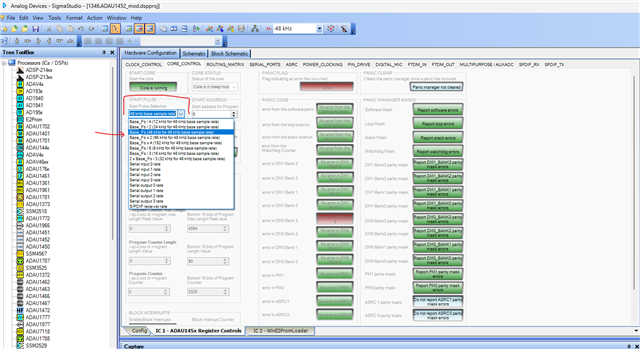
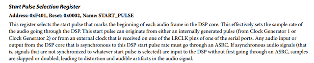
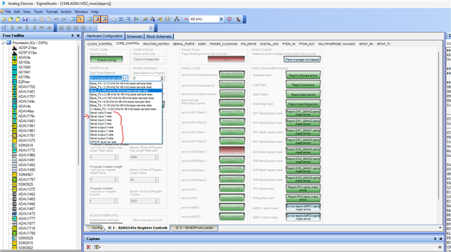
Start pulse is the setting that is used to signal the DSP core to start processing the new frame, which effectively sets the DSP sample rate. It's basically an interrupt than can come from anywhere, it can be generated internally using clock generators (derived from PLL), it can use incoming serial port's LRCLK as a sample rate reference, it can be incoming SPDIF rate etc. Below is where the register is located in sigma studio.
In your project, you set the start pulse as 'Base_fs' which is base rate of clock generator 1 (CG1), and the clock generator 1 is set for N/M= 4/24 = 1/6 which is 48KHz if your MCLK_IN is 12.288MHz and PLL registers are set for default value.
So, your project sample rate is 48KHz that is generated internally (by PLL and CG1).
Now, since you slave the serial input port 1 to MCU, the LRCLK coming from MCU will be slightly different from the DSP sample rate (internal), both can be at same frequency of 48KHz but there will be a slight drift between them. Due to this mismatch, some samples will either be picked up twice or dropped which can create audible distortion.
So, we are using ASRC to capture the serial input clock coming from external domain and convert it to the internal DSP sample rate. So, no samples will be doubled or missed.
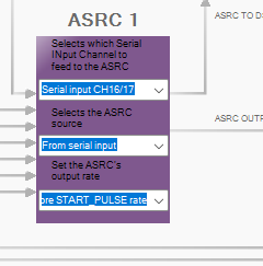
You can see in the ASRC registers that I chose channel 16-17 which belongs to input port 1 where MCU is connected, source to ASRC is serial inputs (port 1 since channel 16-17 are selected above) and ASRC output rate is START_PULSE rate, because that's the DSP sample rate.
One additional note here is that, here the start pulse rate and CG1's rate are just the same, because start pulse is getting its clock from CG1 only. So, selecting 'internal_fs' (CG1's x 1 output) will yield you the same result, but care must be taken that it's not always true.
solonello said:
What confuses me a bit is that it was already working with the standard serial input not going through the ASRC, do you wander why?
Maybe it might have worked for you without any big clicks and pops or notable audio distortion, if you look at the signal in the spectrum, you may find something, because this will always be a problem most of the times. so, we recommend using ASRCs in this condition.
There is another way without ASRC, if only MCU and DSP is involved, you can simply set 'serial input1' to be the start pulse, this way the DSP will start processing the frame once the sample received, nothing will be missed out. This method will not be a problem unless your project is so big that uses almost 100% of the MIPS.
Here is the setting
But it won't work in your case. since you have ADC inputs also coming in, we can't use this method. Because the ADC clock is external to the MCU LRCLK which we set as start pulse (DSP sample rate), so ADC's LRCLK and MCU's LRCLK (start pulse) will slightly drift which will create the same problem. So, you will have to use ASRC for the ADC input to convert the ADC's clock to DSP sample rate (serial input 1 rate from MCU). Here If I mention ASRC's output rate as START_PULSE rate then it means MCU's LRCLK rate (serial input 1) NOT CG1's rate which is why I mentioned 'it's not always true'.
So, if you use CG1 as start pulse then you will have to use ASRC for MCU input. Since ADC and DSP are in same MCLK domain, ADC can a be master, no need for ASRC there.
There are so many ways to setup the clock in this part, it's super flexible.
Hope I have answered your questions.
Regards,
Harish
Please log in to reply.