Distortion with 32bit in and out
Hello
Please help me to confirm few things that is now shown in manual.
If got 32bit source but input port format is set to 8.24. Will it cut it in to 24bit format first the extend by 8bit as a headroom?
As I understand If I would like to have original 32bit processed I need to set input port to 32bit format. and set output port to 32 bit as well to get original 32 bits processed.
I did this, but I have an issue. ones I catch a tiny clip because signal comes from ADC I got unexpected behaviour. Clip part is clipped with distortion that is obvious. But after clip event I got distorted sound on low level signal until I power cycle DSP or reload program. Why?
With 8.24 in and out it works well
ak5572_new_pcb_32bit.dspproj
Audio Signal Processors
hardware
adau1467
SigmaDSP Audio Processors
one more question. It looks Level indicators is made for 8.24 format. With 32bit they always clipped. How to switch Level indication to 32bit format?
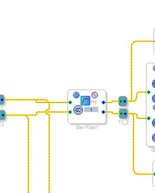
I have found that clipping is coming from high pass filter. if I turn it off it works good. but if I set high pass filter to 1Hz even with 0.5db level reduction it gives distortion. why is hapenning?
Hello Jarr,
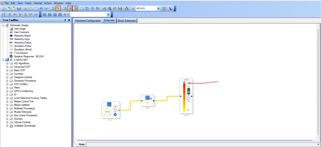
You can click on the below marked area to edit the range; this way you can see signal which is above 0dBFS.
I will get back to your other questions in a while after I have a look at your project.
Regards,
Harish
trouble in this filter. If set below 10Hz. doesn't meter which gain. Some times it can work well for some time. unstable operation.
I need to cut low range, so I can`t remove it.
Hello Jarr,
That is a good question and I actually am not sure. It is an IIR filter so there is recursion in the filter along with multiplication and addition so over time the RMS level might be slightly different.
But, I am glad you mentioned this because that is the first thing I noticed yesterday when I looked at your project. I meant to comment earlier but got sidetracked.
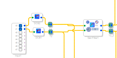
You are being redundant at the very input of your project:
Why do you have the DC block which is a HPF set just below 1Hz only to send it to another HPF set to 1Hz?
You do not need both. One will do the trick of getting rid of any DC offset from the converters. It is great to have at least one but I am guessing that the ADC you are using might actually have a HPF built in! In that case neither is needed!
I see how you are doing the clip detection and it is a decent way to do it. It tells me you understand a lot of what is going on with the numbers.
You are using the Peak Envelope Generators which internally get the absolute value and then accumulate the signal with the decay time. The 500ms hold time you have setup will stretch the pulse output so you can see it with an LED so that is also good.
I have not been able to setup my test bench to exactly replicate your setup especially with the 32 bit ADC.
Regarding your observation about the distortion hanging around for a long time after a clipped event? I would like for you to add an oscillator to switch to as in internal source so you can clip it and then switch to a known good source.
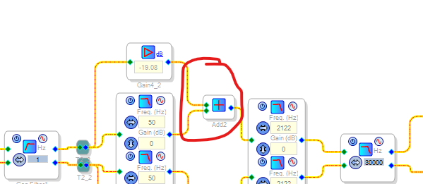
What I suspect is going on is that you are saturating the IIR filters and since they are recursive it is not clearing out. You are operating at the exact top level of the DSP headroom. You are also adding the signal for some unknown to me reason?
So if a signal is coming in that is greater than -20dB below the 32 bit max level in, then it will add 20dB to the signal which will make it clip!! Also, why are you cutting out anything above 50Hz? This means that a 30Hz signal may clip because you are adding it to the -20dB amp signal. Remember that a clipped signal also has a DC component. So I am very confused as to what you are trying to do?
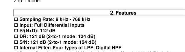
I have a suggestion to try. If you look at the AKM datasheet, Yes, it is 32 bit output but the EOB is nowhere near that!! It is a marketing ploy!
Here is a screenshot of the datasheet:
Not counting the 2-to-1 mode, the best spec is 121dB.
121/6.02 = 20.09966777408638
So basically 20 bits. OK, Let's call it 21 bits!!
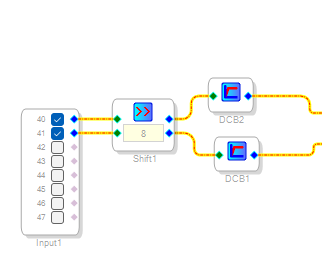
So my suggestion is to take the 32 bit input and right away do a shift right by 8 bits to make it into a 24 bit signal which would align the clipped signal with our normal levels of an 8.24 signal!!
Do this on the input side:
You are not losing any resolution since those lower bits are just noise!
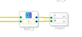
Then before going out of the DSP do this:
You just have to make sure the levels are not greater than an 8.24 signal before you shift it.
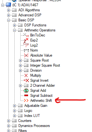
Here is where you find it in the library
It is an arithmetic shift so it takes care of the sign bit for you.
I think you will find this takes care of the issues you are seeing.
Now, one more little thing. I had created this project a long time ago for clipping detection. Although what you are doing is good. I am including it here in case others might want to experiment with other methods.
4087.ADAU1452 Clipping Detector.dspproj
Enough for now!!
Dave T

Thanks a lot for your answer. Very detailed.
Sorry, I didn't tell you what I am working on. It is digital RIAA. This product will be focused on scratch recovery of old discs. So input filter is to remove tonearm resonance. so it should be tuned between 1 and 20Hz. In next step I will attach pot to change the value.
Why do I use to filters in series. It is because of unexpected behaviour of low pass filter. At the beginning I used 8.24 format, And if I set low pass filter to 10Hz it stops to remove DC. So I got confused with that.
Yes, it looks filter is saturating. Please find test project attached. 1256.test.dspproj
If I set 3Hz to the filter, output rises from 0db to +24db.
So how to filter below 10Hz without saturation?
-------------
I am adding signal because it was your RIAA example in an other thread.
-----------------
I wonder if it does the same if I set 8.24 format for 32bit input stream? I thought 8.24 input format does datatype conversion as well as bit cut into 24bit length.
I understand than you example will give me 24.0 data. but precision should be the same. is it?
------------
thanks for you clip project. It gave me useful information.
Hello Jarr,
I had a DUH? moment... you have to be able to laugh at yourself in this field of work! You are multiplying by -19dB so I am pretty sure this will invert the signal so when you add it to the LPF output it will cancel! Anyhow, let me move on,...
I looked at your test project. I am finally able to explain more fully what is going on thanks to something else I noticed that did not stand out at first.
Here is your latest example project with some additions I did:
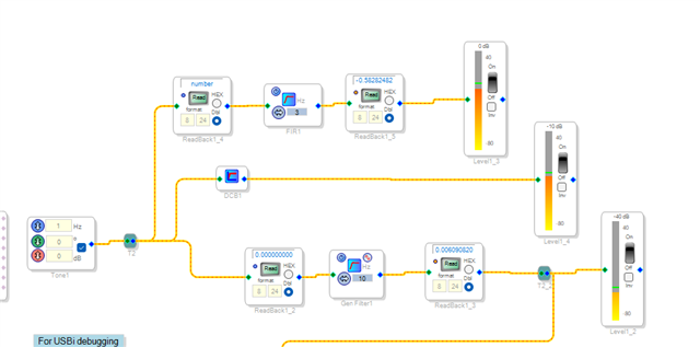
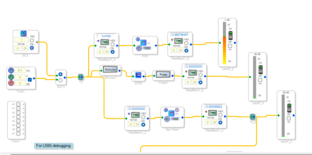
I was able to see that with the filter set to 3Hz and you put in 1Hz you got a high level out!! Notice I put in ReadBacks before and after the filters and I could see the data was sitting at a DC level when I shut off the oscillator!
Then I noticed this,... the project is running at 192kHz !!! This means that even with a double precision filter the 3Hz is so close to DC when compared to the sample rate that the filter is having too much trouble with resolution and the feedback etc. All you have to do to see this is change the sampling rate to 48kHZ and Poof!! problem gone!! Well, instead of this high level of DC I saw one LSB which is insignificant.
I know you want to run at 192kHz so I am not telling you to change that. You either need to not go as low, Notice in my screenshot I had changed the filter to 10Hz and that all functioned fine at 192kHz. When I feed it a 1Hz signal I see some roughly 40 dB of reduction and when I cut the oscillator I only see one LSB.
Then the other suggestion I have is to use an FIR filter! In my changes I pulled in a General FIR filter set to the minimum 2nd order and it worked great. You can raise the order if you like and the benefit of the FIR is the linear phase. But, that is your choice.
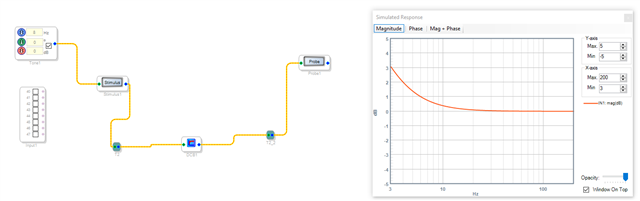
Also, you see in my example I tested the DC Block filter on its own and it works great. It is only a single order filter and the math is a little different so you can use the DCBlock and then keep the other filters at 10Hz or greater and you should be fine.
You see 3Hz is 0.000015625 of the 192kHz FS. VERY close to DC.
I was about to say this: If you set the data format of the input or output block it will not work. Because it only takes 24 bits out of the I2S but.... As I think about it, the I2S is left justified. With our parts that are 24 bit it left justifies the 24 bit data and adds eight zeros below it. So coming in it takes the top 24 bits and ignores the bottom 8. So Yes, I guess you could just set it for 8.24 and the serial port should work fine. I have never experimented with 32 bit converters. Whenever I have had to change to a 32 bit interface I was actually sending 32 bit data! Sometimes I have added eight bits of control data or a different signal to a 24 bit signal.
So I think you could save a few instructions by just setting the ports to 8.24. Yes, the precision will be the same. The 24 bit data will come in as a 1.23 number and be placed in an 8.24 bit word by adding one bit in the LSB position and seven bits at the top and extending the sign bit.
By the way, you are showing your age.... RIAA amp! You are lucky my hair is grey enough (white actually) to know what an RIAA amp is!! I teach in the audio recording programs for two schools here in the Boston area and for the most part none of the students know what an RIAA amp is!!! Every recording studio used to have one back in the day!
Now you want to add a pot to change the value? What value do you want to change? Frequency or level?
Level is easier but frequency is more difficult because it usually requires new coefficients. We do have some filters that are adjustable. I will save that for another post. This one is getting too long.
Dave T
Thanks again for your answer, I enjoyed. Now days it is hard to have any educated support.
ha... really LPF will rotate phase and adding may subtract. But in hardware RIAA net I will use resistor in parallel with capacitor for this stage. I thought it will do the same job... I need to think about that. That might be the reason it sounds a little different from hardware RIAA in low mid range. thanks.
--------------
FIR It was first I think. But I am have never designed FIR filters and design tools I found on internet show that FIR filter for such a low frequency will need a large number of coefficients. If you can show me design way I will be much appreciated.
I need to tune frequency.
---------
I work for 22 years in Hi-Fi audio company doing service and R&D. Nice to meat man familiar with analog wold. Now day all is going to digit. So I decided to design something that can join two worlds. I still got a lot of doubts about quality of which I can achieve because I have to amplify then attenuate. But at least I will not need to search for precision audio capacitors it is hard to find. I worst case I will move 50Hz filter to analog front.
It gonna drain my brain :-)
Hello Jarr,
A couple of comments.
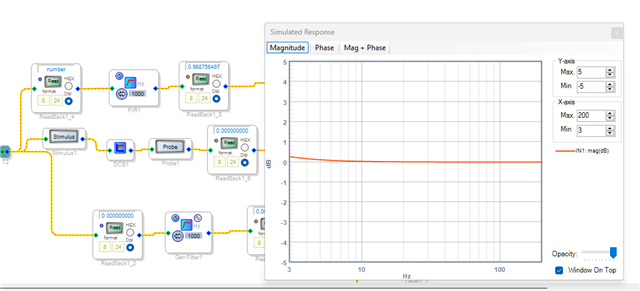
I do not get the same results as you got.
The Probe is covered up but it is right at the output of the DCblock cell.
I have been testing this using actual signals and data generated in the DSP not with the Stimulus and Probe which is all software and none of it is processed in the DSP. It will run into issue when the frequency is getting close to a small multiple of the sampling rate.
This morning I took it one step further in that I added a switch and an actual DC source set to full scale DC to see it be removed.
I am using readback cells which reads data inside the DSP. So does the meter but the meters have integrators with time constants so again, at very low frequencies or frequencies close to Nyquist it will have inaccuracies. You should take a close look at good old analog meters some day! They are horrible and nowhere near flat in frequency response!!
Another thing I have been working on this morning that you should know about. In my screenshots I have the General FIR filter. Well, I had an issue with it but it ended up being user error. The error is in the default filter order. It is set to ten as a default and that is not enough for any lower frequency FIR filter. I will expand more in a past below this one.
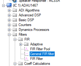
This is where it is located in the library.
The FIR Filter Pool could be an option. I seem to remember using that in the past and that might be a good one for you to use. Because you can setup several filters for the tonearm resonance and select between them.
I will drop in my edited project here in case you want to look at it.
1256_Test_DT_Edits.dspproj
Dave T
Hello Jarr,
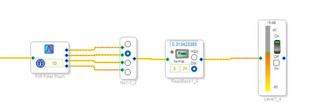
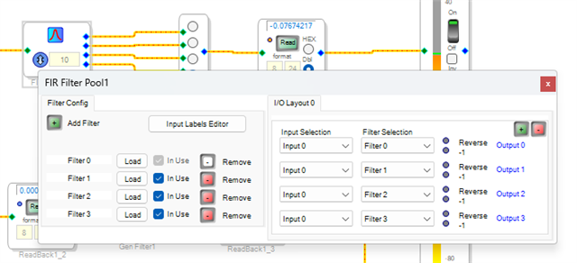
OK, Here is a test of the filter pool block. There are many ways to set this up but I think this will be the best way for you. Just change the switch over to an externally controlled block with slew so that the switching is clean and quiet.
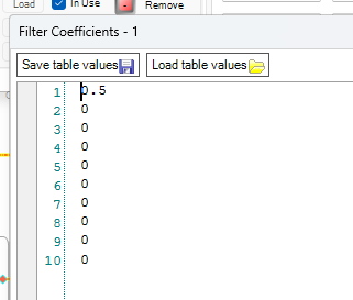
I did not take the time to calculate a bunch of filter coefficients. Instead I just used the first coefficient to change the overall gain.
Filter 0 = 0dB level change
Filter 1 = -6dB of level change
Filter 2 = +6dB of level change
Filter 3 is around -20dB of level change.
So you can see that you are using the different filters.
This is the setup:
Here you can see that filter 1 is multiplying by 0.5 which is -6dB
Here is the program:
FIR_Filter_Pool_Test_DT_Edits.dspproj
Here is a program that shows how to control an index selectable filter using an AUXADC pot. Instead of the filter just use a switch if you want to use the FIR filter pool. You could use this filter as well but it is an IIR filter so it will have the same issues with low frequencies and a high sample rate.
3857.ADAU1452 AUXADC Controlled Index Selectable Filter.dspproj
Enough for today!
Dave T
Never mind about DC block. It got issue with simulation only.
Analog meters is a good memories of back days. Some times I had to bend an arrow to tune it :)
I also tried General FIR today with same result.
Next one is working(I used rePhase software), but it is limited in 9999 taps.(if you enter 10000 it stop working). It is not enough(it is needed about 15000taps) for a high order filter at low frequency.
I found that Shelving filter works well at low frequencies. I can add two in series after DC filter.
Could you explain the difference between versions of shelving filters?
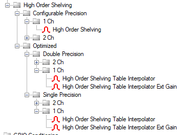
Hello Jarr,
Again, the simulation tool will fall into issues at really low frequencies. At least it does limit the input when you try to set it really low.
High order shelving...
Optimized is optimized for program size. It also allows you to pick between double and single precision. You will need to use double precision due to the low frequency requirements.
Someone here in the company that I consulted with suggested you really should be using a SHARC with floating point numbers. It is not often where it makes a big difference since the DSP core in the Sigma300/350 parts are so good even though they are fixed point but there is a limit and really low frequencies will expose this.
By the way, thar is a huge amount of taps!!! The latency of the filter will be huge!!
Dave T
Hello Jarr,
I need to educate myself and others in the basics of FIR filters!! The earlier reason I saw errors in the General FIR Filter is because the default filter length is too small. It defaults to ten.
Let me show you what you will find:
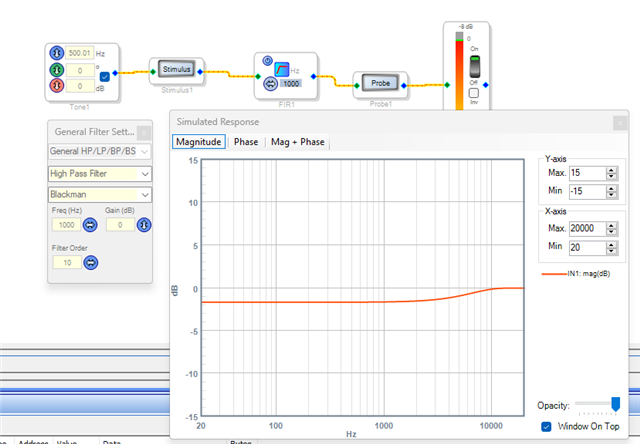
Here is the results at 48kHz FS with a HPF set to 1000Hz and a filter order of 10. This is what you get which is a lousy filter!!
Only about a 2dB reduction below the 1,000Hz filter corner.
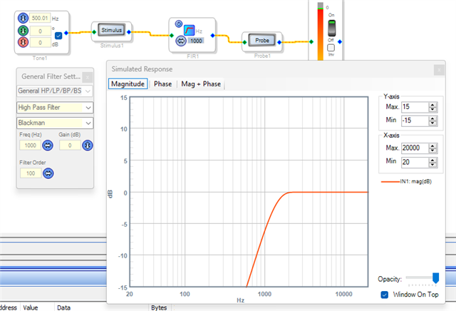
Change the filter length to 100 and this is what you get:
I kept the lower graph set to the same -15dB
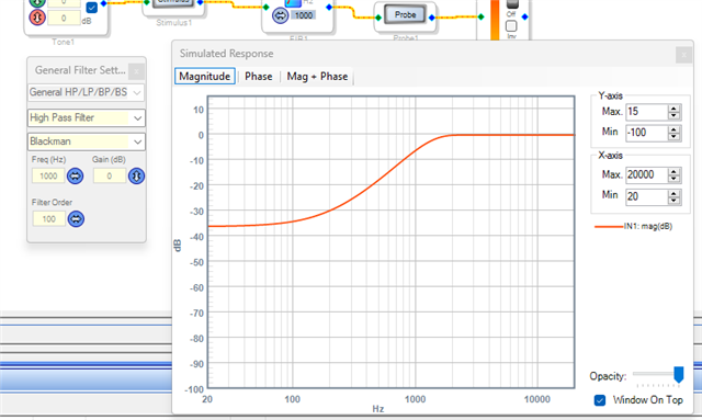
If I change the graph to -100 you can see the attenuation is around -35dB
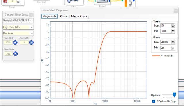
If I change the filter order to 250 now we have a rather good HPF!! -75dB-ish attenuation!
Now this is at 48kHz.
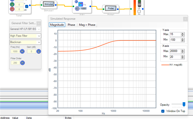
I will keep the filter order at 250 and change the sampling rate to 192kHz
WOW!!! I am back to only about -16dB of attenuation!!
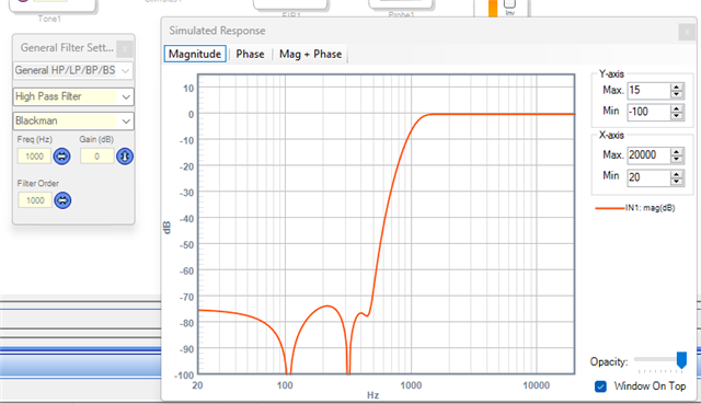
Since the sampling rate was 4X higher, I will change the filter order to be 4X more and this is what I get:
See!! We are back to the -75dB-ish attenuation.
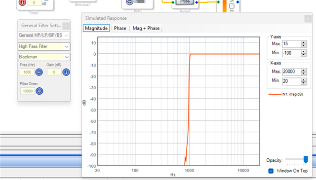
So for low frequency filtering you really need a high order with an FIR filter. The max I was able to set it to was 10,000
You get a nice brick wall filter!!!
But it is using a LOT of memory, 10,000 memory locations! So for many programs it will be difficult to have a filter this large and have enough memory for it.
But, the good news is that the filter is working and works as expected as long as you pay attention to the math and filter theory!
Dave T
Thanks a lot for your research. So it is an issue with terminology. It is not a filter order it self it is the amount of taps.
Fir the next project I definitely will got with DSP C++ programming(SHARC or similar). But for now I am not so clever.
Please log in to reply.