Computing RMS values
I am curious about my measuring methods and interpretation, and wanted to get feedback on what I'm doing.
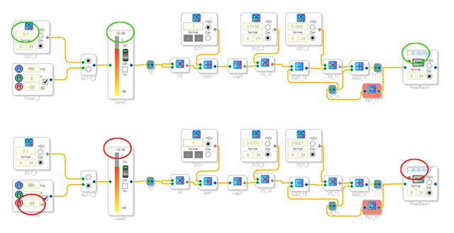
I'm attaching an illustration of a small project. It takes either a DC value or a sine tone as input. It squares, logs and multiplies by a decibel factor, then is low-pass filtered, where I can read its output as what I believe to be its RMS value.
The top example, with a DC input, looks normal. The 0.1 input level would be 20 dB below peak, and this is indicated on both the bargraph meter and on the readback at far right (the green circles).
When I switch to the tone (the lower illustration with red circles), the -20 dB sine indicates as -23 on the bargraph which makes sense, because a sine wave is -3 dB in reference to a DC value of the same peak level. But on the readback block, it indicates a further 3 dB lower than the bargraph, at -26.
I'm sure it's a mathematics thing I'm confused about, but I wonder why the difference.
I'd be very thankful for a quick explanation!
David Reaves
rms
Audio Signal Processors
software
4.7 and earlier
SigmaDSP Audio Processors
adau1466
Show More
Hello David Reaves,
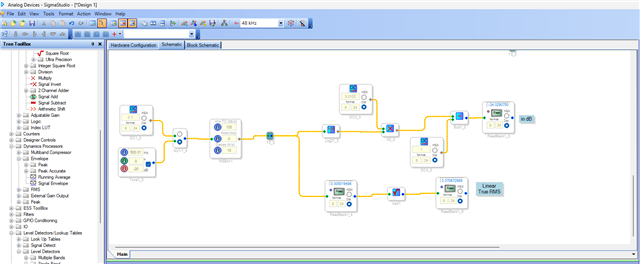
Please have a look at the below circuit which gives you true RMS value and values in dB.
Kindly attach your project, I will have a look and get back to you with what's happening in your circuit.
Regards,
Harish
Here is the project file.
Thanks for your help!AGC experiment2.dspproj
It looks like the MSEnv module (in your drawing) is a squarer, and an adjustable low-pass filter. Not sure the nature of the filter, but it takes up a relatively large number of cycles (24 instruction cycles per sample) for what it does.
Hello all,
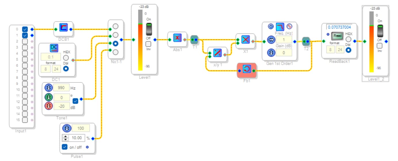
Here's another idea for a True RMS ==> DC Converter. It uses an implicit RMS calculation, shamelessly lifted from the AD636 Data Sheet. The implicit calculation doesn't involve squaring nor square root, thus is simpler, has a wider dynamic range, and can handle higher crest factors:
The 10% pulse has a value of sqrt (10%) = 0.316... If measuring signals coming from a ADC, use a DC Block filter as shown. Audio ADCs often introduce a small DC offset of about 0.005 -- not a problem for audio, yet awful for precise measurements. Finally, for frequency content much above 1 KHz, a higher sample rate may be needed.
Best regards,
Bob
RMS-DC-Implicit-Converter.dspproj
Please log in to reply.