There are serious bugs when generating the MCU configuration file for ADAU1787 using Sigma Studio 4.7.There are serious bugs when generating the MCU configuration file for ADAU1787 using Sigma Studio 4.7.
Hello!
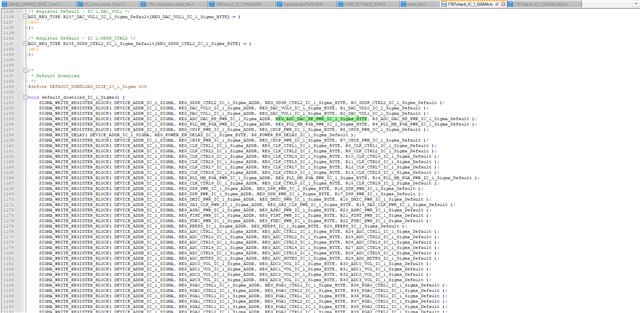
I discovered a serious bug. When using Sigma Studio to generate the configuration file for ADAU1787 (the configuration is quite simple; it's just a DAC output serving as the signal source. I have successfully achieved this using USBi), I found that the content of the exported header file contains a series of bugs. The details are as follows:
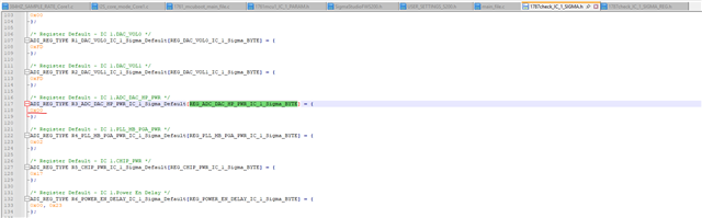
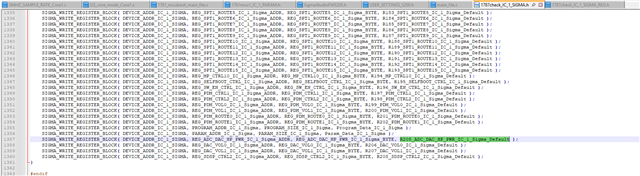
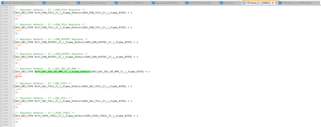
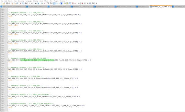
1.A minor bug, many registers, registers ending with "BYTE", such as
"ADI_REG_TYPE R152_IRQ1_STATUS1_IC_1_Sigma_Default[REG_IRQ1_STATUS1_IC_1_Sigma_BYTE] = {
0x00
};" in "ADAU1787_IC_1_SIGMA.h",The REG_IRQ1_STATUS1_IC_1_Sigma_BYTE is defined as 0. There are a total of 24 such errors. Please excuse me for not being able to list them all due to my busy work schedule.
Obviously, this does not conform to grammar and cannot be compiled.But the problem is, should I modify it so that it can pass the compilation, or should I simply delete it directly? I noticed that the data manual clearly states that there are specific requirements for the order in which the registers are written.
2. A very serious bug:
You definitely won't believe it, but the generated header file is missing the initialization of some registers, which directly causes the MCU to fail to start the DSP. For instance, the cores of SDSPL and FDSP did not perform any operations at the beginning and end of the initialization process. Theoretically, they should have been initialized after writing the values into the registers and then stopping. The reason why I consider this issue serious is that I cannot determine exactly how many registers have not been initialized, and whether the writing sequence is correct?
This is the problem I encountered in my recent work, which has taken up a lot of my time in troubleshooting. I hope you can take care of it.
sigma studio
software
ADAU1787
sigma studio 4.7
Integrated/Special Purpose A/D Converters
SigmaDSP
Audio CODECs
Show More
Hello DrCai,
DrCai said:
1.A minor bug, many registers, registers ending with "BYTE", such as
"ADI_REG_TYPE R152_IRQ1_STATUS1_IC_1_Sigma_Default[REG_IRQ1_STATUS1_IC_1_Sigma_BYTE] = {
0x00
};" in "ADAU1787_IC_1_SIGMA.h",The REG_IRQ1_STATUS1_IC_1_Sigma_BYTE is defined as 0. There are a total of 24 such errors. Please excuse me for not being able to list them all due to my busy work schedule.
Sorry for the trouble, I can see the bug with the exported files.
DrCai said:
Obviously, this does not conform to grammar and cannot be compiled.But the problem is, should I modify it so that it can pass the compilation, or should I simply delete it directly? I noticed that the data manual clearly states that there are specific requirements for the order in which the registers are written.
This is the bug in exported system files, and it has nothing to do with DSP running or compilation related.
This will be a problem when you export the system files and try to access register from an MCU, the obvious work around would be manually editing the value to be '1'. I understand it's tedious, but we have no way around it.
Most of the required registers like PLL, serial clock registers, MPs, ASRCs etc. are exported properly but only few sets of registers have this problem that we have to change manually.
DrCai said:
A very serious bug:
You definitely won't believe it, but the generated header file is missing the initialization of some registers, which directly causes the MCU to fail to start the DSP. For instance, the cores of SDSPL and FDSP did not perform any operations at the beginning and end of the initialization process. Theoretically, they should have been initialized after writing the values into the registers and then stopping. The reason why I consider this issue serious is that I cannot determine exactly how many registers have not been initialized, and whether the writing sequence is correct?
For this, some of the registers which uses its default value (unless customer wants some different setting and changed that registers in GUI before compilation) are not initialized in the file and sigma studio won't even write to those registers, because most customers go with the default value so sigma studio doesn't bother writing the default value again, instead it let the registers use its default value which will reduce the SPI/I2C traffic. But if customer wants a register specific setting, then they would change it in the GUI, then sigma studio notes that down and when you link compile download, those registers will be written with the new value (other than default value, i.e value customer set in the GUI), now you can see that particular register is updated in the capture window and when you export the files, you will be able to see it in the header file.
Just change the register you said was missing to different value and link compile download the project, you will be able to see that register in capture window and in exported files. Kindly let me know if it works.
I hope I understood your query correctly, if not please give us some more info regarding it or steps to simulate it. We will try simulating it in our end and get back to you.
Regards,
Harish
Thank you Harish !
Previously, I could load programs using USBi. However, after exporting the configuration file and making modifications to the first minor issue, using MCU boot DSP still didn't produce any response. Therefore, I believe there are other unknown problems. Currently, I haven't achieved using MCU to start DSP. The MCU is operating normally, and the boot signal can be captured through the logic analyzer.
May I ask if you haven't tried starting ADAU1787 using the MCU either? If possible, could you please explain to me the contents and sequence of other operations after the configuration? I used to use MCU to start ADAU1401 before. At that time, there were no problems. Just writing directly via I2C or SPI was sufficient.
Once again, thank you for your help, Harish, have a nice day.
Hello DrCai,
Thanks for the information.
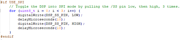
Are you using SPI or I2C? If SPI, you will have to toggle the CS pin of the control port three times to put the DSP in SPI mode, then only you will be able to write to the DSP via SPI.
In sigma3xx DSPs, if you select SPI in the USBi module, then sigma studio will generate the three toggle commands to put the DSP into SPI mode that you can see the transactions in the capture window. But I can't see anything like that in ADAU1761 or ADAU1787 DLLs, so I suggest you add that little code snippet in your code. Below is the snippet.
If I2C, then you can send the commands directly. Make sure you add the pull up resistors in the I2C bus and addressing is correctly done with ADDR pins.
The IOVDD of ADAU1787 is 1.8V maximum, so your MCU should output the same logic level.
DrCai said:
May I ask if you haven't tried starting ADAU1787 using the MCU either?
The MCU I have outputs 3.3V IOVDD and I didn't have a level translator right now at the bench, hence I can't try this now. But I will be able to help you with some debugging steps.
DrCai said:
If possible, could you please explain to me the contents and sequence of other operations after the configuration? I used to use MCU to start ADAU1401 before. At that time, there were no problems. Just writing directly via I2C or SPI was sufficient.
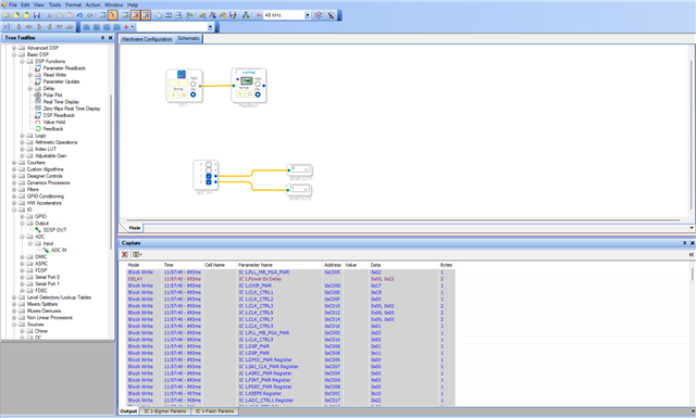
Okay, Let's try one thing. You said that you can program the DSP via USBi just fine. So, just create an audio pass thru project and compile it. Now the working sequence is captured by capture window in correct order.
Just click the first transaction and press shift and scroll down to the bottom of capture window and click the last transaction, now full capture window transaction is selected (Ctrl + A won't work here).
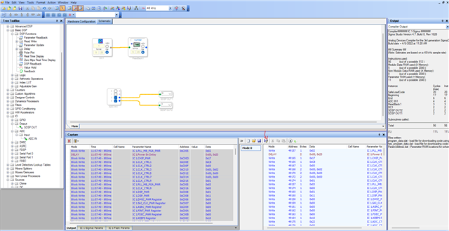
then right click and select 'add to sequence', then your sequence will be added to sequence window like below.
then just export the C files by clicking the icon I marked above.
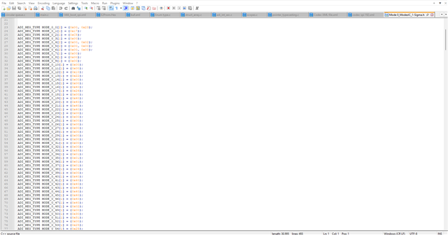
Here we are just exporting the needed registers for the project to run and PM, DM data. You will get the below file.
In this file, the required registers for the project are exported and array size and values are hardcoded. You can't have any bug here and we are just having the same register values and PM, DM data that sigma studio sent to the DSP which worked fine. So, if you send these commands from your MCU, the DSP will boot up fine.
Please implement the delay required between writes, you can refer the capture window for it and the delay function is included in the MCU examples in the wiki.
Let me know how it goes.
Regards,
Harish
-----------------------------------------I have identified the reason. Please scroll down to view the answer from 2025/08/05.--------------------
Hello Harishgowtham,
Since the product being manufactured did not have the USBi pins reserved, and the default operation was for the MCU to start, I have now gone back to investigate this issue.
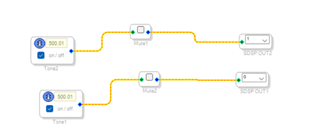
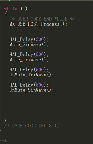
Briefly describe my experimental framework. The MCU communicates with the ADAU1787 via I2C using a 3.3V-1.8V bidirectional level converter. It controls the DSP through I2C. At the same time, there is also IIS communication between the MCU and the ADAU1787. The ADAU1787 restores the clock using BCLK through PLL. I have implemented the USBi programming, the function of repeatedly switching the mute module by the MCU, and the I2C is pulled up. Therefore, I can temporarily assume that my hardware part is fine.
Then, following your instructions, I exported all the "capture" files under Sigma Studio and placed them into my MCU file.My code consists of two parts. The first part is the initialization section, and the second part is the section where the mute module is repeatedly turned on and off within the while function.
First, I disconnected the I2C interface. After initialization, when entering the repeated switching mode, I reconnected it. At this point, the oscilloscope showed the results. The sine wave was jumping back and forth during the repeated switching, indicating that there was no problem with this part and the content within the while function.
But here comes the important part. I reset both the MCU and the DSP, meaning I used the MCU to start the DSP. However, there was no result at all.
What's more interesting is that I conducted another experiment, which was to reset only the MCU and not the DSP. This means that when the DSP is operating, all the initialization controls need to be rewritten from scratch. As a result, on the oscilloscope, the previously repeated switching of sine waves has now turned into nothing at all! I found a project shared by a net friend online. I placed his initialization file into my MCU startup file (which is a direct routine), and it worked successfully.
So I think the problem lies in the initialization code, but I directly used the code from the file exported by SigmaStudio.
I contacted that online friend. He told me that there were problems with the export of SigmaStudio 4.6 and 4.7, but 4.5 was fine. However, I also used 4.5. For the same program, my export failed to be successful. He also forgot which specific version he used. So I think there might have been a previous version that was acceptable. However, in the subsequent version updates, the initialization of the registers and the changes might have caused problems.
I will attach my SigmaStudio project file, the direct routine file that the aforementioned netizen was able to successfully run (he did it about two or three weeks ago, and has forgotten the exact version. He claims it was V4.5), the startup code file exported by SigmaStudio, and my MCU startup file.By the way, I am using the latest version V4.7 from the official website.
Could you please take a look at them for me?My PCB product is configured with the default MCU startup and no USBi interface is reserved. Therefore, I can only start it through the MCU.
Regards,
Cai
MySigmaDSP_Project.zipSuccessfully_launched_project.zipMy_output_initialization.zipMCU_BOOT_Function.zip
---------------------------------------------------2025/08/05---------------------------------------------
Hi,
Harishgowtham,
I already know where the problem lies. It's the same serious bug I mentioned before. I request that you fix this bug as soon as possible.
I monitored the I2C signals that were burned into the ADAU by USBi and MCU using a logic analyzer. After organizing and analyzing the data, I discovered the following issues.
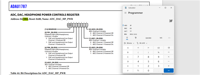
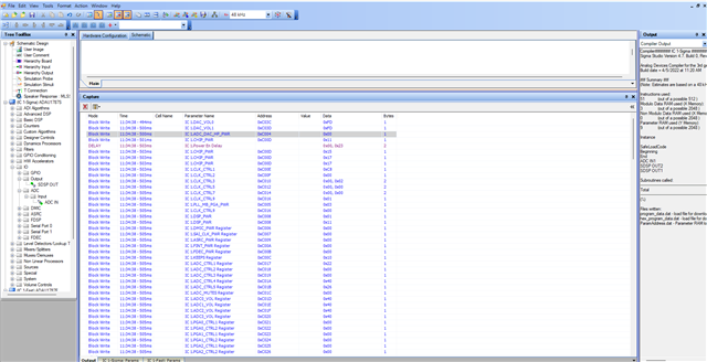
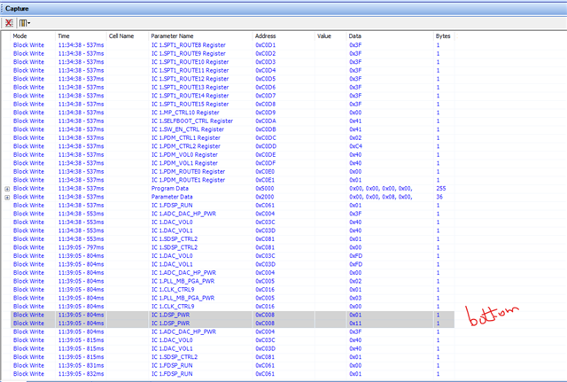
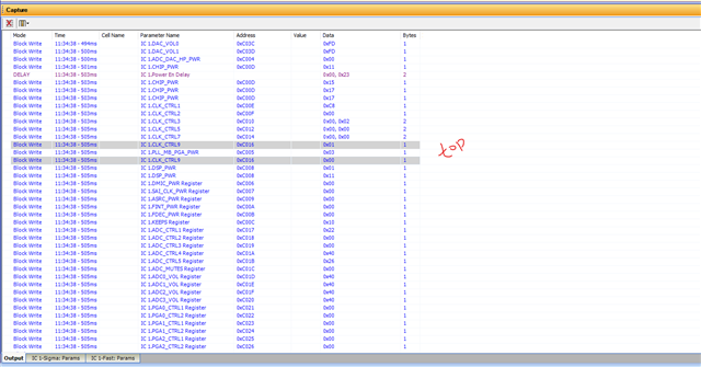
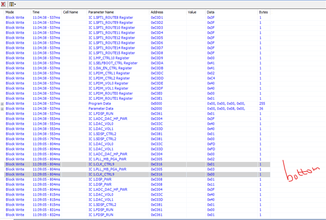
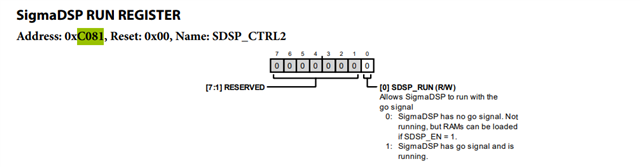
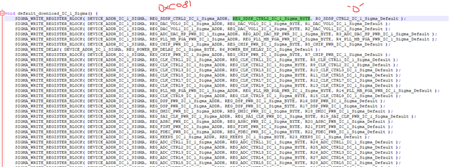
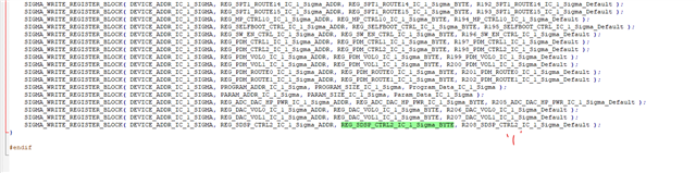
The reason why the MCU fails to start normally is that both the beginning and the end are missing the configuration for the registers 0XC004, 0XC005, 0XC008, 0XC016, 0XC03C, 0XC03D, 0XC081, and 0XC061.
But, Why???
Here comes something interesting
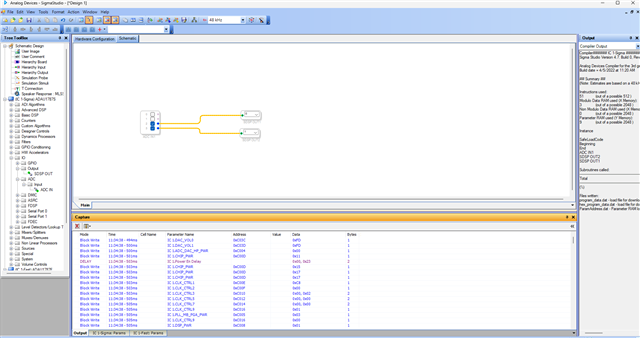
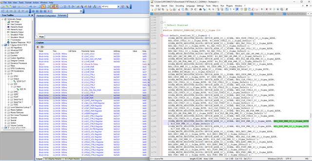
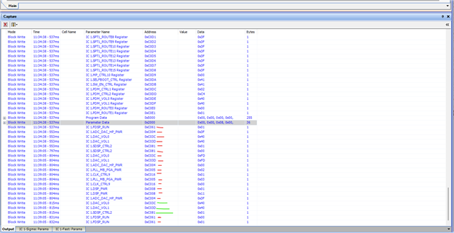
When exporting the file, the "Capture" column shows the following content. It is obvious that there is a module called "Delay".
You can test it yourself. When you export data above the "Delay" level, all the data you get is empty!
Moreover
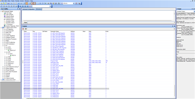
When you reach the end, there are two configurations, namely for the program register (0x5000) and for the parameter register configuration (0x2000). However, in this subsequent configuration, all the settings for FDSP, SDP, ADC, and DAC are completely invalid, and after export, all of them are empty.
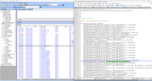
But the more serious issue is not just at the head and tail; there are also cases of missing register exports in the middle, such as 0xC008, 0xC016, and 0xC061.
I conducted a rough check and it seemed that the values in the program registers and parameter registers that were exported were also incorrect. They were different from the burned-in values of the USBi that I captured.
The absence of register exports is likely to affect the program registers and parameter registers.
I request the authorities to quickly fix this bug.
Thank you
DrCai


Hello DrCai,
DrCai said:
You can test it yourself. When you export data above the "Delay" level, all the data you get is empty!
I can see that there are some issues when we export the files from the sequence window (capture window transactions copied to sequence window), as you said a few registers at the top and bottom were missing when exporting from sequence window.
But the usual way of exporting system files seems to be correct to me. That is when you 'link compile connect' the project and click export icon next to 'link compile download' button.
Below is your observation and what I can see from the exported files.
DrCai said:
I monitored the I2C signals that were burned into the ADAU by USBi and MCU using a logic analyzer. After organizing and analyzing the data, I discovered the following issues.
The reason why the MCU fails to start normally is that both the beginning and the end are missing the configuration for the registers 0XC004, 0XC005, 0XC008, 0XC016, 0XC03C, 0XC03D, 0XC081, and 0XC061.
But, Why???
You said these registers were missing in the exported files.
I created a basic project and exported the files. My schematic is very simple, just a pass thru. I didn't enable any hardware registers.
The register 0xC004 which is ADC_DAC_HP_PWR register, you can see that the register is included in the register write, at first, it's written to '0'.
after writing all registers, DM, PM, the 0xC004 is written to '1'
sigma studio does the same.
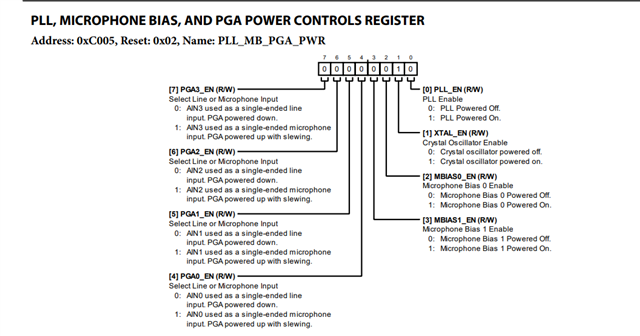
for the register 0xC005,
it's written to 0x3 which is enabling the PLL and crystal oscillator.
for register 0xC008,
SS writes couple of registers twice (one at the top and another at the bottom), but with the same values.
It's NOT like disabling a register at the top and writing to memory, other registers etc. and enabling that register at the bottom. SS writes same value twice which is avoided in the exported files.
Take this 0xC008 register as example,
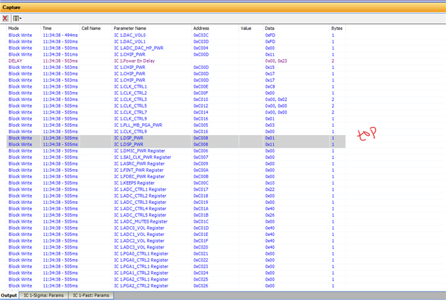
At the top, it's written to '0x1' and the next line it's written to 0x11, again in the bottom it's written to 0x1 and in the next line it's written to 0x11.
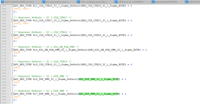
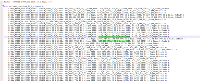
But in the exported files, it's only written once at the top with the same value. If you think this is what that causes the issue, then you can place these two writes at the bottom of the exported files.
The same with 0xC016 register, it's written twice in SS but again with the same value and written only once in exported file.
For the register 0xC081,
It's written to '0' at the beginning and after writing everything to memory and registers, it's finally written to '1' again, so the DSP will start running.
After the parameter data is written, below are the register writes given in SS.
But the writes I marked in red are written twice. For ex, take registers 0xC03C and 0xC03D, both registers are written to 0xFD at the top, now in the bottom (after param data), it's changed to 0x40, after couple of transactions it's again written to 0xFD and then again written to 0x40. There are three transactions at the bottom and value ended up being 0x40.
In the exported files, it happens only once. at the top it's written to 0xFD and in the bottom (after param data), it's written to 0x40.
So, I marked (in red) all registers that are written twice in SS, if you neglect those registers and see the rest, there are only four register writes that I marked in green.
If you look at the exported files, only those four register writes are given in exported files after the param data write.
So, if you think these missing (the second write with same value at the bottom) registers are the reason for the boot failure, then did you just try copying those registers from the top and pasting them again at the bottom (in the same order as SS) and see if it works?
I don't think this is the only reason for the boot failure.
Please let me know if manually placing these register writes again at the bottom makes the sigmaDSP boot from MCU.
Regards,
Harish
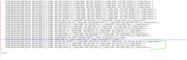
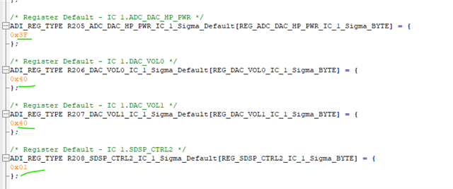
----------------------------------------------------------------------------------------------------
2026/01/07
Hi, Harishgowtham
I have solved this problem
The problem is that the FDSP is not enabled. Although I only used the SDSP, it needs to be functioning properly, and both need to be turned on simultaneously.
Also, a few months ago, you mentioned the issue of needing to manually change some registers. Specifically, several zeros need to be changed to ones.
It is now functioning properly. Thank you for your guidance. Thank you again.
Please log in to reply.