Using additional ADAU1466 core for added DSP resources for higher order ANC
Hello again, I'm back with a new question.
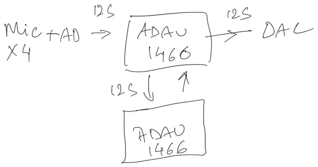
I've attached a block diagram of what I'm attempting. basically I'm trying to use an additional ADAU1466 core to add DSP resouces because I want to use longer filter length and higher DSP sample rate for a multichannel ANC (using MFxLMS library function)
partial dual channel ANC SLAVE.dspprojpartial dual channel ANC MASTER.dspproj
Here's what i thought would work but it doesn't quite work as I had hoped.
in brief what 1 is set as master with all clocks as master, and the other as slave with all clocks as slave and master clock disabled.
greatly appreciate any help.
dualcoreADAU
Audio Signal Processors
hardware
SigmaDSP Audio Processors
multichannel
adau1466
Show More
Hello suncha300,
I can quickly see a few things in your projects.
1) You configured all serial ports in I2S mode.
You can't use channel 34 in stereo mode; it can only be used if you set the serial output port 2 in either TDM4/TDM8 mode.
2) The same thing in the slave project, Serial input port 0 is configured in I2S mode, so channel 2 can't be used unless it's in TDM4/TDM8/TDM16 mode.
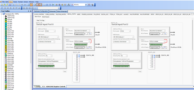
3) In the slave project, the serial input port 0 and 1's LRCLK is set as master whereas BCLK is set as slave.
Since the master DSP is providing BCLK and LRCLK, the slave project's LRCLK is also set as master, this will create conflict in the bus.
The slave DSP's MCLK is coming from Master DSP's CLKOUT right?
So, now are you facing issues with audio passing thru between these master-slave DSPs? or the performance or noise related issues?
Please give us some more info about the issues you are facing.
Regards,
Harish
thank you so much for the prompt response.
The LRCLK on the slave set as master was a miss (intension was to change it to slave).
one baffling thing was
32(master) - 0 (slave)
33(master) - 1 (slave)
34(master) - 2 (slave)
became
32(master) - 2(slave)
33(master) - missing
32(master) - 0(slave)f
changes made :
LRCLK to slave on slave board
I2S output 2 on Master changed to TDM8
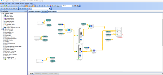
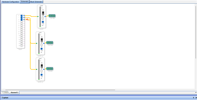
signal out of Master going to channel 32, 33 and 39
I2S input 0 on slave changed to TDM 8
signal from master in channel 0, 1, and 7
now it is setup as I had intended, while master handles retrieving and sending peripheral signals, along with processing, the slave will process what master sends it to process and then sends back.
I haven't completely run my program yet, I'm hopeful that this will add processing power without affecting performance of either of the board.
Gratitude!
Sunny
.
Hello again,
Update: Duplex communication between the two ADAU1466 boards is now successful. This is a step forward: I have managed to get the microphone input from the second board (the Secondary board) processed within itself. This means one serial port on the Secondary ADAU1466 is configured as the clock source for the two microphones (with the mics' LR select configured for channel 0 and 1 of that serial port). The rest of the serial inputs and outputs on the Secondary board are set to operate in synchronized mode to receive the serial clock signals for operation. This configuration functions whether or not the MCLK pins between the two boards are connected. This is a confusing result, but as it does not block progress, I have continued.
For the ANC, I'm using the MFxLMS for the ADAU1466. The configuration described above works flawlessly when the secondary path training is active. In this state, the Secondary board receives the input signal from the Primary, sends its output signal back to the Primary, and the Primary performs its function correctly (all in a standard, default configuration). However, as soon as I change the MFxLMS block to runtime mode (in secondary board), it fails without any change to the hardware.
When I check the serial port tab and perform a "Read This Page," I observe that the clock signal settings have changed. All serial inputs are changed to synchronized mode, including the serial input 0 (for the mic input) that was the clock source. Furthermore, all serial outputs are changed to clock source mode, including the output port used to return the signal to the Primary board. The blue light on the board also blinks as if the board was reset. This occurs even without the Primary board connected, meaning without any external clock signals present. This suggests an internal conflict.
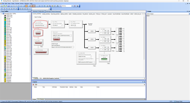
My understanding is that I should disable the MCLK output on the Secondary board and set its "PLL CLK SRC" to "Direct from MCLK pin" when connecting this pin to the Primary board. I have done this, but I am seeking clarity: Doesn't using the MCLK from the Primary board provide the clock signal such that the Secondary board's serial ports, when set to be a clock source, can generate their signals? If the PLL is disabled, can serial input 0 (the mic input) still generate its clock signal correctly?
Please help me investigate the error in my approach and troubleshoot this issue.
2 Reference ANC with Error return and output send from and to primary processor .dspprojThis is the project for the Secondary processor.
6825.Design 1.dspprojThis is the project for the Primary processor.
PS Words matter, kindly provide an update on the software with inclusive words (ez.analog.com/.../adi-words-matter)
Hello suncha300,
Your secondary DSP project doesn't seem quite right to me.
You will have to use the PLL to achieve the DSP's full efficiency, for that you will have to set 'PLL clock' as the source. If you set 'direct from MCLK' then you will be running the core 24 times slower (if your MCLK_IN is 12.288MHz) and the CG outputs will also be slower which means the serial port clocks will not be correct.
So, set that register to 'PLL source' and enable the PLL settings.
Now, I believe the primary DSP's CLKOUT pin is connected to the MCLK_IN pin of the secondary DSP, is that correct?
You can set the secondary DSP's serial output port (port3) as main and primary board's input port 3 as subordinate, that will give you a good timing. since both board works at the same MCLK domain, you don't need to use ASRC's in the primary board (if the input is coming from secondary board). so, you can remove that.
suncha300 said:
When I check the serial port tab and perform a "Read This Page," I observe that the clock signal settings have changed
Do not perform 'Read this page or Read all register' which is quite troublesome, that will change all set registers.
suncha300 said:
Doesn't using the MCLK from the Primary board provide the clock signal such that the Secondary board's serial ports, when set to be a clock source, can generate their signals? If the PLL is disabled, can serial input 0 (the mic input) still generate its clock signal correctly?
When CLKOUT from primary DSP is disconnected/disabled then secondary DSP will not have a MCLK, hence that DSP will become brick, it will not function. so, that part must have stable MCLK all the time for it to function properly.
if possible, send a block diagram which shows MCLK, inputs and outputs between boards with clock directions.
Your primary board project is fine with register settings; it takes input from serial input port 3 and set as subordinate which is fine. I think this is coming from secondary board's serial out port 3 to primary board's serial input port 3. if it's, then you don't need an ASRC, and white noise is sent out on output port 3 of the primary DSP which is set as main which is also fine.
In your secondary board project, serial input 0 is main and receives mic input and serial input 3 is subordinate that's receiving the white noise from primary board. which is all fine so far (apart from the PLL section) and this is what is visible from your projects. I think the DAC or speaker is connected to primary board's output port, is that correct?
so, your configuration between boards would be fine if you correct that PLL sections I mentioned above.
suncha300 said:
However, as soon as I change the MFxLMS block to runtime mode (in secondary board), it fails without any change to the hardware.
what exactly failed when you changed to runtime mode? doesn't it work as expected?
Please describe your issue with the MFxLMS block.
Regards,
Harish
Please log in to reply.