S/PDIF output is it "bit shifted" ?
Hi,
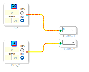
quick background to what I am doing - I am working on an S/PDIF receiver in an FPGA so I want to generate a good S/PDIF signal that I can trust and also that I can control what it is outputting, so I have put the following into an ADAU1452
I have a host CPU with an SPI interface that can write into the DSP's memory and so by writing to the "data" location of DC5 or DC5_2 I can explicitly set the data stream that is coming out of the S/PDIF (I'm ignoring all the User Bits at the moment).
BUT: what I am seeing is that the LSBit is being ignored, that is, if I write '1' into the register the output waveform does not change. But if I write 2 into the register then the first bit of the output waveform changes as would be expected for the typical bi-phase encoding.
I can go through all the other bits 4, 8, 0x10 etc. and they appear in the output as expected but the overall appearance seems to be that all the bits are shifted down by 1 place with the LSB being lost.
It seems as if the SpdifOut "algorithm" expects data in I2S format (1-bit shifted) but I can't find anything in the documents to confirm this so:
Can anyone shed any light on what I am seeing ?
Am I correct in thinking that SpdifOut should be driven with I2S format data ?
Is this selectable ? I've looked in SigmaStudio but I can't find anything.
Many thanks in advance for any advice and asistance.
PhilipJ
Audio Signal Processors
adau1452
hardware
SigmaDSP Audio Processors
Hello PhillipJ,
This is detailed in the datasheet but you can watch me detail this in this video:
Serial Port Data Transfers
Yes, the LSB is thrown away on purpose. This is not an error.
Dave T
Hi Dave,
thanks for your reply, sorry I missed it in the datasheet but I always enjoy watching your tutorial videos :-)
It's good to know that it wasn't my AES3 receiver design that was losing the LSB. I've been bitten by that sort of thing before, you know where you design the transmitter and the receiver and test the latter with the former. Make the same mistake in both and you think everything is working sweetly! hence I wanted to test my RX with someone else's TX.
I can modify my test implementation to shift the data up by 1 bit as it loads into the SpdifOut so that the data I write is what comes out.
Kind regards
PhilipJ
Hello PhillipJ,
Just be sure to check full scale voltage. I do not exactly remember if the mapping of the data coming in is the same as the serial ports where the 24 bit data will come in as a 1.23 number and end up at a 1.24 number. So you would not have to shift the data. If you shift it you might end up with a head room issue.
Oscillators in the DSP are setup to put out a full scale 1.24 number. So if you route it to the SPDIF output it should not be clipping and it should be at full scale so if you gain it up 1dB you would get clipping/.
Try the same thing if you have an AP with an SPDIF output at a known level. See what it looks like in the core.
Dave T
Please log in to reply.