SigmaDSP running 32kHz - no interface support
Hi,
I want to run the SigmaDSP in 32kHz sample rate as I'm running out of MIPS. 24kHz samplerate is too low signal bandwidth. Is that posible? I can select it in the SigmaStudio, but I can't select it in any of the interfaces like ADC, ASRC, FDEC, etc. only 48 and 24k is possible.
Best regareds
John
hardware
ADAU1787
Integrated/Special Purpose A/D Converters
Audio CODECs
Hello John,
It would be handy to know a little but more about your system. Are you using the fastDSP? Do you need to have it be the smallest latency possible?
What is your signal flow in the part? Are you using the ADCs and the DACs and the serial ports?
There are some settings to run the SigmaDSP core at an external rate like the serial port but then it would mess up the ADC or the DAC timing.
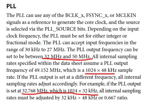
The easiest way is to adjust the PLL output to be slower. This is actually mentioned in the datasheet. It explains your actual situation.
Then the text in the register settings would not be correct but the actual frequency in the text would be times 0.667.
So this means the fast DSP would be running a little slower.
Dave T
Hi David
Thank you so much for the reply. I see how busy you are in this forum.
The project is using the FastDSP and I'm using the SDSP to control the path from mics to speaker. Additional I have a analogue input from ADC mixing into the mic signal. There are no hard requirements on latency other than "low" :-), below 100uS, target 20-50uS with analogue mic. I tried digital mic and it seems there is much higher latency for that input type - decision is to go with a good analogue MEMS mic.
Currently I'm running 192kHz in the FastDSP because there is also constrains on power consumption. Probably going up to 384kHz later on.
The 32kHz proposal/question is only to get more processing cycles. As I see your answer it's not going to help on that. Am I correct?
It's related to this post: Multible compressor curves - saving MIPS
and this is taking up some MIPS: Design support for AGC funtion
Thanks a lot for your support.
All the best
John Hammer
Hi Dave,
Am I right in that the in the PLL system will not give me more instruction cycles? Only way is changing 24kHz on input input/output side and in the editor?
Best regards
John Hammer
Hello John,
Well, this all depends on the clocking setup and there are some limitations or things you need to pay attention to. If you have the serial ports set to be a master clock and gets its clock from the internal source then the sample rate will be divided from the internal system clock. So this will be the internal MCLK divided by 1024 for 48kHz etc. So you will get 1024 instructions per frame.
However, if you have the serial port slave from an external clock source and it is running off of a different crystal or MCLK source then the two rates will not be exactly the same. So if you set the core start pulse for the SDSP to be the serial port then in that case if the incoming rate is slightly slower then you will get more instructions for that frame.
The SDSP Rate clock is what we call the Start Pulse on the other sigmaDSPs. It tells the core that it is the start of the frame so start running the program! The instructions are executed from the internal MCLK which might be a little faster so you get more instructions for that frame. If the incoming clock is faster then you get fewer instructions than 1024 in that frame! This is why for applications where you are slaving from an external clock you do not create a program that is just able to fit into 1024 instructions. There are frames where some instructions will never be executed. These instructions tend to be the moving of data to the serial output port or the DACs. So you lose output for that frame. The old sample is repeated.
The 49.152 MHz PLL output frequency that will give you correct divided outputs of 48kHz,... etc. Is close to the max PLL output frequency of 50MHz. So you could push it up a little and maybe get around 800 more instructions per frame or you run the incoming sample rate a tad slower than 48kHz.
The problem is that the ADCs can ONLY run on the internal sample rates. So if you play these tricks you have to use the sample rate converters if you run the ADC directly into the SDSP. the FDSP can also slave to an external clock but you have the issue with the ADCs.
So there are some pitfalls and of course power dissipation is increased. But, you might be able to squeeze out a few more MIPS.
Another pitfall is if you run the FDSP on the internal rate then the sample rate is slightly off so your filters will be slightly off on frequency.
I cannot say this is condoned or recommended. I am just answering your questions. I would not run the PLL output faster than 50MHz. as stated in the datasheet.
Dave T
Thanks Dave,
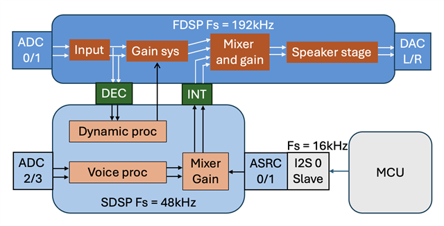
Just made this simplified drawing to give you an overview.
The FDSP and interfaces is running 192kHz and should not be lower - higher is fine.
The SDSP and interfaces is running 48kHz now and could be lower - but 24kHz is too low.
What would be possible? I can't go outside the recommended specs.
It's not a problem to recalculate filters and timing.
All the best
John Hammer
Hello John,
Wow, this is tough. Thanks for the diagram.
I wish this part had more clock generators like the Sigma300/350 parts do then you could run the core at 44.1kHz which would give you a few more instructions. I do not see an easy way to do this.
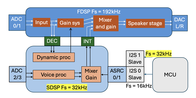
I will give you some "if's" and I do not think any of these are good ideas. You could up the MCU sample rate to 32kHz from 16kHz then set the core rate to the incoming I2S rate. But this has its own problems. You would have to use an ASRC for the ADC 2/3 but you would not need it for the MCU. Then you would have more instructions and the core clock can remain as it is and the FDSP can remain at 192kHz fs.
Another possible option would be to run a clock into the other serial port and only use that to drive the core rate. This clock could be at 44.1kHz or 32kHz whatever you like. However, I am just thinking out loud here and have NOT tried this in the lab. You would need to mock this up and try it out before committing to it. I am not sure if these ASRCs can get their in and out rates properly. The register settings do not seem flexible enough to do this. It looks like the output rates have to be the internal clock rates which will mess this all up.
I wish a bit more flexibility was designed in. This part was designed with one thing in mind, headphones. So low power was the driving design goal so features and extra stuff was removed.
Dave T
Hi Dave,
I'm been busy with other stuff....
I have updated the drawing with what I understand could be a solution. Is that correctly understood?
Best regards
John
Please log in to reply.