Creating crossover DSP gives wrong outputsignals
Trying to create a speaker crossover with ADAU1452.
Tried to use different signal filters but none give a proper output signal.
The most straightforward should be the Filter (Filters/Crossover/Double Precision/2-Way/Crossover)
I set a crossover point of 450hz and type LR-12.
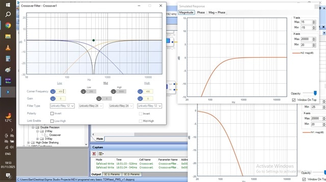
Using the stimulus/probe shows that the output doesn't follow the curve like expected and show on the filterblock
The curve from the stimulus/probe dont have a -6db at 450hz.
At 450Hz the Low pass filter is almost -25db iso -6db
The High pass filter has a -6db at around 120Hz where it should be at 450Hz.
Measuring my speakers with the signal provided with this filter show the same slopes as with the stimulus/probe function.
How can I get the proper result as it should be and shown in the crossover filter screen?
Audio Signal Processors
adau1452
software
4.7
SigmaDSP Audio Processors
Hello Bart-Luyckx,
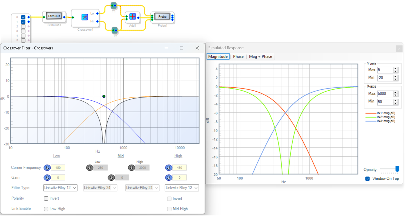
The project below shows the correct response for each crossover filter as well as for their sum. I right-clicked the Probe to add more inputs. Comparing this project to yours may reveal the cause of your differing results.
Best regards,
Bob
Thanks Bob,
My project is similar to yours.
I find out that it is clock related.
When I set system sample rate to 48KHz all is fine.
I dont know what are the correct settings for 48 / 96 / 192 KHz
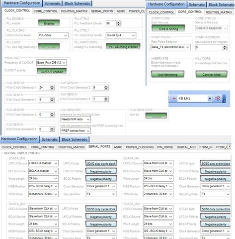
These are my current settings.
I would like to use 96kHz
Hello Bart-Luyckx,
You're correct that the issue here is all about sample rates. SigmaStudio uses the sample rate setting atop its schematic window to set up the blocks in your schematic to work at that sample rate, but does not set the DSP chip to operate at that rate. Filters, oscillators, and timers need to have their own sample rate match the chip rate. Thus, when your filter is set for 96K but the chip is running at 48K, its frequency is half what it should be. And wrong config settings can make it half again, or 112 Hz instead of 450 Hz.
It looks like you already have the correct settings for:
Clock control (same as for 48K)
Core control (start pulse = Base FS*2)
The core runs at the same calculation speed for 48/96/192K. Doubling the start pulse frequency halves the DSP calculation time between samples, in turn halving the project size.
We also need to get the audio in and out at the higher sample rate -- for 96K, set the sample rate for serial input and output port(s) in use to 2*Fs
In addition, your codec chip itself must also be set up for 96K. I believe some of the popular 3rd party DSP / amplifier boards have a way to set this up for you. Are you using one of these or designing & prototyping your own board? In general, codec setup involves consulting the codec manufacturer's data sheet and programming your system micro to load the codec's relevant registers via its I2C or SPI interface.
The attached sample project has the DSP and serial port settings for SDATA IN0 and SDATA OUT0. I ran it on my evaluation board and it does show audio data at twice the speed compared to the 48K version of the project. However, I can't tell if it actually works because my evaluation board's AD1938 codec is hardwired for 48K. I added a 440 Hz oscillator as an easy way to check sample rates -- if you hear 440 Hz (middle A), the HW and software rates are a match.
Best regards,
Bob
2-way_1452_96K.dspproj
Thanks Bob.
I need to dive into the hardware more.
I have ADAU1452 / CS42448 combo from aliexpress. I think it is set to 48 in/out. When i change the fs from the serial input tab I dont get any output signal. Only when it is 48hz.
Anyway i tried to do some more testen with the 48kHz for now.
I tried to meause different crossover freaquencies. When i have a high crossover point the inpuls measurement looks ok.
But when i lower the crossoverpoint the signal looks strange and corrupted.
here some impulse measurements. the measuring conditions are the same.
I make the measurmements indoor with a 5ms window. (200Hz)

This could be from the phase mismatch between the hi and low outputs near 450 Hz — note how this shows in the crossover window. With the LR12 crossover you need to invert either output, which you can do within the window. Then you’ll see the two outputs total to a flat response, and your measurements should improve.
As for the 96K issue, I’m afraid I’m not familiar with the board that you’re working with. Check the board manufacturer’s website for a sample 96K project. If there’s any, download one and get it to work, then modify a copy with your own application. Failing that, you could start a new thread and upload your project — perhaps an ADI support engineer or another member could check the 1452’s HW settings. Yet I suspect that since this board uses a non-AD codec, your best support would be from the board manufacturer’s website or user group. Sorry I’m not equipped to work the problem with my eval board.
Hello Bart,
I agree with what KJBob has been saying. This other codec is not running at the correct sampling rate so it will all be a mess. You need to look up in the codec datasheet how to change the sampling rate. It might have a stand-alone mode where you set it with pins. You might be able to set it with register writes but then the DSP needs to be connected to it and this will turn into a very long thread.
You have to see how the connections are made on that PCB. Do you have the schematic?
We will need that and your project to see if there are other issues with settings.
Dave T
Just to make things a bit more clear.
I'm using 48khz clock settings.
Using the crossover function, the slopes set, I measure them at the correct frequency.
This is the case for all frequencies I set (8khz, 2khz, 450hz) and LR12, LR24,... All looks correct.
I only measure the low part of the filter. Just 1 channel you see in the above impulse window.
I don't know why the impulse measurement is so different for 450hz crossover. This is the case with the crossover function, but also happens with any kind of low pass filter I use.
When the measurement window is shrinked or expanded the amplitude of the fr changes below the crossover frequency.
I'm using REW for measuring.
What is happening here?
Hello Bart,
Please supply your project.
Also, what are the clocks going to the DAC?
What is the DAC setup for regarding sampling frequency and serial format?
Dave T
Please log in to reply.