multiple units in the same circuit
Hey Folks,
this may some crazy, but is there any reason I could not use multiple 1701's in the same project?
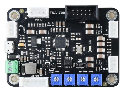
I picked up a handful of the little "tinysine tsa1700" project boards, I'm wanting to make a crossover with multiple time align outputs.
first unit handles a two-way crossover plus a sub out (with a delayed out)..
second takes the "hi" output and gives me four different delay outs..
third takes the "low" output and gives me four different delay outs..
Or something along those lines..
I don't see a way to combine all three into one sigmastudio project, so I'll make different projects, but is there any concern feeding the output of one card straight to the input of another?
JohnR
hardware
adua1701
processors and dsp
Processors and Microcontrollers
adau1701
This should work, with a little clever effort.
Search for Analog Devices AN-1006, where it even describes multiple ADAU1701 chips on the same board.
You can drag multiple 1701 blocks/modules into your SS project. They'll each get a different IC number, and when you build the processing, each module will be assigned to a specific module. You'll have to plan which processing is on each chip.
I don't know whether the TSA1701 exposes the serial port digital pins on headers, but it would be ideal if they do. Otherwise you'll be connecting the boards through a chain of ADC/DAC/ADC/DAC/ADC/DAC/ADC/DAC/ADC/DAC
When connecting the serial output of one (primary) 1701 to the serial input of the other (secondary) 1701, you should make the output ports be the master clock, and the inputs ports would slave to the incoming clock from the other.
On that note, ideally your primary 1701 would have a crystal or oscillator on XTALIN/MCLK which then drives its CLKOUT pin. Set the registers for the primary 1701 as appropriate for this clock source. In your circuit, connect CLKOUT of the primary 1701 to the MCLK input on the next 1701, and then set the registers for the secondary 1701 so that it expects the clock. Note that MCLK cannot be higher than 36 MHz, so choose something like the typical 12.288 MHz on the CLKOUT of the primary to the MCLK input of the secondary.
You can load the primary and secondary EEPROM images with their separate chips. I have not tried this, but you would right-click on each 1701 in SigmaStudio, and write through to its corresponding EEPROM. The TSA1701 will need to be able to disable SELFBOOT during this, and then set SELFBOOT later for startup.
You probably can't have SigmaStudio run a combined schematic for multiple SigmaDSP chips if they're all on separate boards with separate programming headers. However, you might be able to make a fanout-board that takes a connection from a single USBi, and then has five output headers for your TSA1701 boards. You'd want to connect all four extra SPI Slave Select lines that are not on the ribbon from the USBi to your fanout board, and then route each unique select to the appropriate programming header. Each TSA1701 would think it's SPI 0x01, but the USBi will be talking to SPI 0x01, 0x02, 0x03, 0x04, and 0x05.
I may try to whip up a PCB for this fanout board...
https://oshpark.com/shared_projects/Faw0XgDS
This has not been tested, but you should be able to order the PCB from OSHPark at low cost, solder six shrouded headers, and then use AN-1006 as a guide to hand-wire your USBi to J0. With this, you could build a SigmaStudio project with 5 TinySine TSA1701 boards all together.
well gee, thanks for all the info, and this would be handy if I was laying out a pcb from scratch..
but as I said, I have several of these little pre-made boards, and my only real question was;
" is there any concern feeding the output of one cards DAC straight into ADC of another"?
I have no schematic of this little premade project board, but from the parts count on the board I assume they are using the passive style of output filtering (looking at the examples on the adua1701 datasheet)..
Looking at taking one DAC output from the first board and feeding a ADC to one second board, and another DAC from the first board and feeding a ADC to the third board.
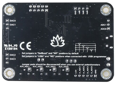
they have not brought the serial ports out to a header, just the two inputs and four outputs, along with four ADC's for using either four board mounted trimpots, or removing some solder jumpers to use external pots. and they only brought 3 MP's out to a header (MP1,MP4, MP5)...
Primitive, but I thought I could make it work...
Yeah, I realize that I started writing my response from the point of view of you having more access to the signals. I hoped I had edited that out as much as possible, but I see it was still confusing.
However, my final assessment was that you could build the PCB that I linked to, and use it between your Analog Devices USBi programmer, and then the PCB would allow you to plug in up to 5 TinySine TSA1701 boards at the same time. SigmaStudio would then allow you to build a giant 5-SigmaDSP design in one project, and download the firmware separately to each individual TSA1701 without as much trouble as would be needed without the adapter.
I assume that despite the limited connectors on the TSA1701, it must still have the 10-pin SPI Control Port for programming.
Another idea is that you might be able to avoid chaining the audio through all the cards by splitting the original audio and feeding it to most or all of the cards. With parallel processing, you might have to duplicate the crossovers multiple times, but that would probably sound better than having a long chain of A/D/A/D/A/D/A/D/A and I'm sure each of these TSA1701 cards can do a lot more than one crossover without running out of processing cycles.
e.g. Your example was to have the first card do a simple 2-way crossover, and feed the "hi" to the second card for delays. I'm suggesting that you feed the second card the original audio and just put a redundant 2-way crossover in the second card, so that the "hi" signal is available there. This will allow your analog path to ideally have only one ADC and one DAC in the path.
ok, so parallel the input to all 3 cards and have each card handle "its" crossover band and delay outs...
I suppose I could just have just one project with with my full crossover, and delays and whatever else,
and have a software switch that determines each cards crossover function.
and yes, it does have the USBi port, failed to mention that..
I'm not so concerned about the need to build one giant sigma project and having the multi USBi interface, but that is a nice option.
Please log in to reply.