Mirror image of the compressor gain level
Hi,
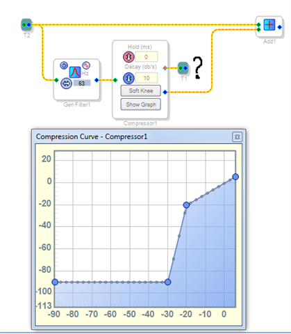
The diagram shows a circuit that, when a certain threshold is crossed, adds a bandpass filter tuned to 63Hz to the signal.
I'd like to add a complementary circuit, meaning one whose gain is the mirror image of compressor 1. If compressor 1 attenuates the signal (e.g., the gain is 0.1 or less), the gain in the mirror circuit is 1, and vice versa. If compressor 1 has a gain of 1, the gain in the mirror circuit should be 0 or nearly 0.
The main question: how do I achieve this with minimal use of mips?
Please don't say "use a second compressor," because that's obvious :)
Thanks,
Best regards, Kuba.
software
Hello Kuba,
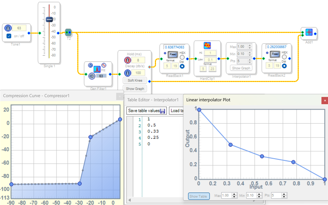
A reciprocal function would make the complimentary gain inversely proportional to the compressor gain. This in turn usually needs a divide function. I don't see which chip you're working with, yet if it's the ADAU1701 -- its divide block eats MIPS like a T-rex. I would suggest using a Linear Interpolator instead, as shown below. The best part is you can edit the Interpolator's table to get whatever function needed.
I included a Clipper to limit the Interpolator's input to the two Compressor gains you mentioned -- 0.1 and 1.0 -- yet you can allow a wider range as desired. Be sure that the Interpolator's input range (its Min and Max settings) covers the entire range you're allowing in, to prevent overrange problems.
Of course you can add more points to the Interpolator graph (and thus more lines to the table) to increase accuracy. Yet you'll never get the mathematical accuracy of an actual reciprocal (divide) function. If you need this, see the Implicit Divider in this thread. Of course if your DSP is an ADAU1452 or higher, its divide block can be used directly.
Interpolator-Gain.dspproj
Best regards,
Bob
Thank you, Bob.
That's exactly what I was looking for. The accuracy needed is either 1 or 0. So, none at all :)
It works.
Please log in to reply.