ADAU1701 self-boots and registers verify correctly, but Sdata_out0 (MP6) never outputs any data
Hi, i would need some help on my custom ESP32 + ADAU1701 schematic, i am stuck at an unusual issue and i cna't progress past it, please read below, will provide more info if needed, just say what that is.
Setup: ADAU1701 (48-LQFP), self-boot from external EEPROM, MCLK=24.576MHz/512xfS, I2C addr 0x34.
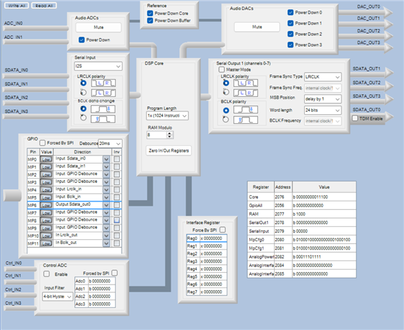
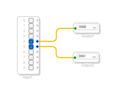
I am using external ADC and DAC - PCM1808 ADC in, PCM1502A DAC out. MP0=Sdata_in0, MP1=Sdata_in1 (spare, used for testing), MP4=Lrclk_in, MP5=Bclk_in, MP6=Sdata_out0. 48kHz project.
Symptom: No audio ever reaches the DAC, i just get one ver brief noise or cut off sound which by ear isn't more than 100ms long on power up only or when I reset the ESP32 which also controls the Reset and Selfboot on the ADAU1701.
Self-boot completes and the DSP answers on I2C every time. But MP6 shows zero toggling activity (GPIO edge-counter on its test point — expect tens of thousands of edges/sec at 3.072MHz BCLK, measured: exactly zero, always), even when I bypass the ADC completely and inject a synthetic tone straight into MP1 by ESP32.
Already ruled out, each independently confirmed:
Sample-rate/MCLK mismatch — fixed, no change
Mute bits (Core Control DAM/ADM) — fixed, confirmed CR=1/DAM=1/ADM=1 by I2C readback, no change
PCM1808 as the cause — bypassed entirely via MP1 tone injection, still flat
Registers loading wrong from EEPROM — read back DSPCTRL/SEROCTL/SERICTL directly over I2C after a real self-boot, exact match to intended config
Bad DSP unit or bad EEPROM programmer — reproduced identically on a 2nd board and with a 2nd programmer
Serial Output port clock source (MP10/11 vs MP4/5) — tested both Master mode (with MP10MP4/MP11MP5 physically bonded per datasheet spec) and Slave mode, no change either way
Current relevant registers: DSPCTRL=0x001C, SEROCTL=0x0000, SERICTL=0x00.
Question: With self-boot confirmed good, registers confirmed matching intent via direct silicon readback, and the output port's clocking tested both ways — what else gates whether the Serial Output port actually shifts data out on Sdata_out0? Is there a precondition or sequencing requirement that wouldn't show up in a register-content comparison?
Can share the .dspproj and full register dumps if useful.
I am not sure what I am missing here, there is obviously something.
hardware
processors and dsp
Processors and Microcontrollers
dsp&processors
adau1701 sigmastudio
dsp audio
Show More
Hello schotkky,
Have you run this program directly from SigmaStudio using the USBi? Are you able to do that on your hardware and if you can then does the program work when running the DSP that way?
This has to be something simple... Please attach your project so I can take a look.
Dave T
Hi Dave
Yes I have ran the program via USBi with a simple pass through for the DSP as a test, I even tried two different USBis with same results, on two identical boards, I have 5 prototypes. Programming procedure for which I don't use live tuning seems to work and what I do is Link Compile Connect, and then right click on the ADAU1701 and Write Latest Compilation to E2PROM, then Check Latest Compilation vs E2PROM for which I get READ/WRITE SUCCESS, which seems to check out every time.
The setup is the following:
- I don't use the built in ADCs and DACs so I have turned them off
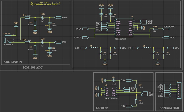
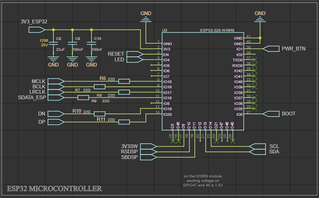
- EEPROM is designed to be programmed with both the ADAU1701 and ESP32 held in reset and non active while USBi programmer is attached via custom H1 header. On the schematic available pins on H1 are 5V, SDA, SCL and GND. The USBi also powers the board while programming, main power source is detached for this. The other two pins on it are RESET to hold ESP32 in reset to free the I2C lines, and the EN5V to enable 5V to 3.3V LDO to the DSP, ADC, DAC and the EEPROM since they are on separate power rail from the ESP32.
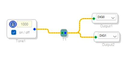
- I tried injecting 1kHz tone generated by the ESP32 (also tested this tone with a loop back to ESP32 to confirm tone is being generated), and the DSP's Sine Tone generator with same result, only get one very short bleep which sounds like quickly cut off 1kHz tone (as sure as I can be on this considering how short it is). This is on each start and reset and that's it, afert that is complete silence.
- The DSP's Reset and Selfboot are also controlled by ESP32 while held low as default untill pulled high by the ESP32, as seen in the attached schematic. The SDOT on the DSP schematic is just a test point for data out for which I am waiting a basic scope to arrive to test if needed.
I read somehwere that probably MP10 and MP11 need to be on LRCLK and BCLK respectively, added those wires by hand (MP4 to MP10 and MP5 to MP11), but no change. Do MP10 and MP11 need to be physically on this bus connected I just described and their correct setting in Register Control? They are not wired in my original design as seen on the schematic.
I hope it's something simple, I have been troubleshooting this for days now but didn't get anywhere so far, it's also my first time working with a DSP. Let me know if more information is needed or other schematic sections.

Please log in to reply.