Reading Duty Cycle from ADAU1466 MP pin
I want to read in a signal to ADAU1466. I have this signal connected to either MP or AUXADC pin through resistor stuff options.
The signal has the following four possible options:
high
low
1kHz square wave (50% duty cycle)
1kHz square wave (25% duty cycle)
What is the most computationally efficient way to read in this signal to ADAU1466 and give a 2 bit response of which signal option is present? A SigmaStudio example would be helpful, if possible.
Thanks!
Audio Signal Processors
mp pins
SigmaDSP Audio Processors
auxadc
adau1466
Hello,
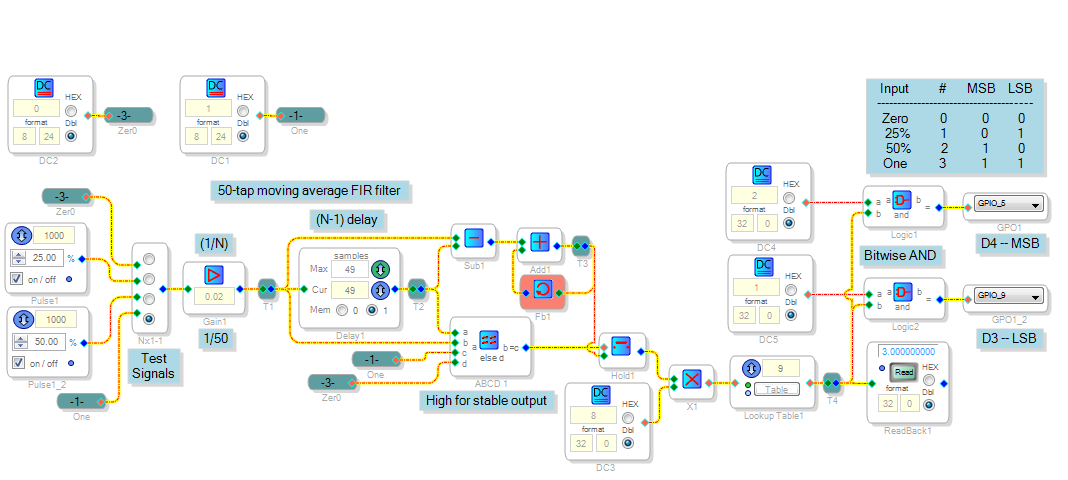
The Philadelphia 76ers ended their season on a 16-game winning streak -- and naturally, a Last 10 (L10) of 10-0. My basketball-following friends look at me sideways when I refer to the L10 as a "10 tap FIR moving average digital filter," but this is what makes it so useful. Suppose the season continued and the 76ers lost one game, followed by more wins. Their L10 would drop to 9-1, and stay there until that one loss exits the far end of the filter. This no-surprises response makes the moving-average filter a natural for measuring a PWM duty cycle. The implementation shown below uses some data memory for its necessary delay, but economizes on MIPS -- see
Recursive Moving Average Filter
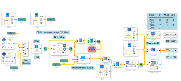
The filter averages the incoming signal over 50 samples, or just over one mS. This is enough to cover the 1 KHz period -- if necessary, make the filter longer to accommodate the lowest anticipated square wave input frequency. Its output trends toward the input duty cycle. To minimize output disturbances as your input changes, a data hold updates the result only when the delay's output equals its input -- the filter's output is stable then. The filter's length determines latency from input to correct output.
The lookup table selects an output from 0-3 according to the filtered result. As shown, its output increases with duty cycle, yet you're free to choose any output code as desired. The bitwise ANDs provide the two-GPIO binary output -- bitwise logic is handy for microcontroller-like functions such as this. The project runs on the new -1466 evaluation board. When you substitute your external signal (via GPIO or aux ADC) for the test signal, condition it so the averaging filter sees a signal range from 0 to 1, like the test signal. Likely you'll want to switch off debouncing on this input pin.
Best regards,
Bob
Bob,
Many thanks! Helpful and amusing explanation!
Evan
Please log in to reply.