ADAU1701 DSP setup error.
Hi.
I would like some confirmation on a rather serious issue I have been observing regarding the setup of the ADAU1701 SigmaDSP from an external MCU.
We have been using this chip for about 2 years and are ready to send our first product with this DSP to the market very soon. But, we have recently been observing that after configuration, the DSP outputs "random" noise instead of the actual audio signal.
This does not happen every time we boot the system, and we have only seen it on ~5% of the final products, so there is not any apparent consistency in the behavior we are observing.
I have seen that, when the DSP starts up normally, the Interface Register data are all 0x00, while when the DSP starts up in the Error state, the Interface Registers are different from 0x00. We don't use these registers at all. And it shouldn't affect our setup since we don't use the Selfboot mode. But there is 100% consistency of the Interface Register data values and the good/bad behavior of the DSP.
What we have found is that when writing the program and parameter memory data to the DSP during initialization after a reset, our previous approach of writing only to the part of the memory, which is actually used, can in some cases trigger this error. Changing the configuration to write all the remaining parameter and program registers to 0x00 (as it should be by default) fixes the error.
How can this be the case? I get that, if there is some random data on that part of the memory, the DSP program can be corrupted and would result in unpredictable behavior. But why isn't this part cleared after a reset?
Our setup consists of an external MCU that configures the DSP via I2C. The MCU is also controlling the DSP reset and a power switch to the DSP to reduce standby power consumption. Please note that this configuration has been working for us since the beginning. So how can this all of a sudden become a problem once we begin mass producing?
Luckily, we have found this fix to the problem since the result is rather catastrophic - we use the DSP to adjust the volume also, so once the DSP starts outputting random data at full-scale, the acoustic shock is rather extreme :-)
Audio Signal Processors
interface register
SigmaDSP Audio Processors
external mcu
adau1701
Hello JTJ,
There may be a couple of different issues at play here. I really should look at your schematic and ask you more in depth details about your startup procedure. So I will send you an email.
The things I am looking for is how you are gating the power to the device and what are you doing with other digital pins connected to it. What is easy to miss is that if you power down the part and still have clocks going to the device, or have something like the WP pin pulled high, it is a problem. The problem is that it violates the max voltage on the pin which is IOVDD + 0.3V. If IOVDD = 0 then the max voltage on the pin would be 0.3V. A pull-up to 3.3V would forward bias the ESD diodes and the part remains partially powered up. So there is not a complete reset and it may also affect the PLL.
So this may be part of it. The way around this problem is to use level translators on every input that has signals or is pulled up. One side of the level translator would be on the main power domain that is always on and then the DSP side of the translator would be on the gated power domain. So when it is off there would be no signals going to the DSP.
Your question about the interface registers is a good question. I will actually have to check on that. It is designed to read the values from EEPROM when it selfboots so the program should not go through and clear it once it starts running. Then it would clear the saved values defeating the purpose of the registers. So I think you will have to clear those on your own. Remember that to write to these registers requires that bit 6 in the DSP Core Control Register be set.
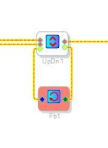
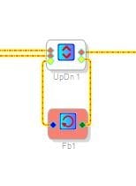
You can do this trick to avoid the interface registers altogether.
This uses modulo RAM that does get initialized to zero automatically. The downside is that it uses one word for each instance so if you are on the edge of MIPS for your project then this might not be good.
This also brings up a question. How many MIPS is your program? What sample rate are you running the core at?
Dave T
Hi Dave.
Thanks for your fast reply.
If you send me an email, I will send you the relevant parts of our schematics.
We are running the DSP with a 12.288 MHz MCLK, with a sample rate of 96 kHz - program length set to "2x (512 instructions)". The PLL mode pins are set with PLL_MODE0 to GND and PLL_MODE1 to VDD. The WP pin is pulled low directly to GND together with the SELFBOOT pin and the ADDR0 and ADDR1 pins.
We are, in fact, keeping the IOVDD (pin 18) on, while powering off the remaining sections (PVDD, AVDD, DVDD, VDRIVE). But, reviewing our schematics again, I have noticed that the VDD used for holding PLL_MODE1 high is also switched on and off. The same is the case for PLL_LF (after the filter). Could this be an issue, when IOVDD is always on?
I have tried to clear the Interface Registers on my own (with bit 6 in DSP Core Control Register being set), but with the same result. I am not even sure that the data on these registers are causing the issue - it might just be another symptom of the same problem.
Can you verify that we have to write all 5120 bytes of program data and 4096 bytes of parameter data during configuration, to make sure that these sections does not hold random data at the remaining unused parts after a reset? Or should it just be cleared to "all zero" if the reset has been done correctly?
We are quite close to the max on MIPS in this configuration, as we are using 508 of 512 MIPS.
Hello JTJ,
I think your program may be just a few instructions too long. There is an overhead but I have never been able to get a definitive answer to exactly how much is needed. I will send an email and send over your project so I can see if there may be some instructions that can be squeezed out.
Dave T
Please log in to reply.