adau1701miniz eval board frequency response
Hi,
I'm testing the adau1701miniz eval board and getting a strange frequency response characteristic. Using the analog line level inputs and outputs, the output has a high pass response with a corner frequency of ~2khz, -12db per decade.
The test setup includes just an audio precision unit in addition to the evaluation board. I've configured the DSP to directly pass through the analogue in to corresponding outputs attached to the output TRS jack.
Would anybody have some advice as to what I'm missing here?
Many thanks in advance.
Hello,
It wouldn't hurt to hang a scope on the board's output to verify that its waveform is clean and not in clipping. Although the ADAU1701 is not intended for instrumentation applications, its ADCs and DACs actually work down to DC.
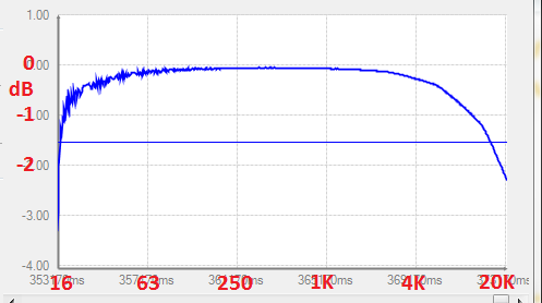
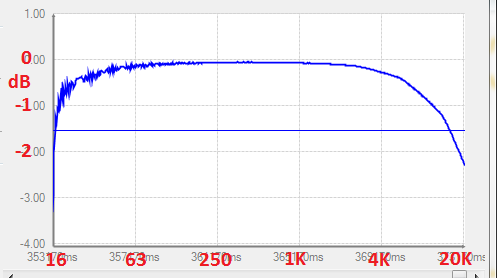
This is the 1701MINIZ response I measured at 48K sample rate, using a ADAU1452MINIZ board to make the measurement:
Best regards,
Bob
Hello wctronic,
Now, I have seen this many years ago before I worked here at ADI. I used to test lots of gear with my audio precision and what I found is that sometimes there was an error in the interface between the AP and the DUT. The output of the AP is a transformer and when I used a TRS signal in some devices only the tip and the sleeve were connected. So what you got was a transformer with one side dangling. All that got through was high frequencies since there was a lot of stray capacitance and not much loading. So I would go into the AP setup and change the output to single ended (un balanced). You also have to pay attention to this on the output side. I would run an unbalanced signal to pin 2 and 3 of the XLR and then leave the shield telescoped from pin one of the XLR to shield the cable but not tie it on the unbalanced side. I had made some XLR-M to XLR-F barrels to adapt to these wiring schemes and carried them with me.
What you are describing is exactly what I would see,,,, no low end!
Keep in mind that the 3.5mm connectors on the eval board are stereo and wired like a headphone, tip-left, right-right, sleeve-ground.
See if this makes a difference.
Dave T
Hi Dave,
Thanks for the reply,
I ended up making some single ended BNC cables and this worked perfectly fine. Definitely a mistake on my end setting up the test equipnent.
Please log in to reply.