ADAu1466 with I2C Selfboot memory and PCF8574 IO Expander
Hello.
How to configure ADAU1466 for I2C selfboot and external IO Expander PCF8574?
First I would like to use PCF to change input source for codec, and second reason to use I2C is delay setting for TPA5050 chip.
PS. There are any recomended I2C memory chip for ADAU1466?
Audio Signal Processors
SigmaDSP Audio Processors
adau1466
Hello traxman,
I am looking into an example for you but it will be difficult for me to test this without the I/O expander part connected. We are still adding to the Master Port capabilities and this one is a little tricky to realize right now. So I will work on that.
Meanwhile, I have to ask Why do you need the TPA5050? It has 170ms of delay per channel for two channels. The 1466 has a lot of memory on-chip for delay. It has 1600ms of delay if you do not use much of the parameter RAM for anything else. So any decent sized program will use up some of that but I think it will be difficult to use so much that there is not 340ms left over. I guess if you were to use a large number of FIR filters but still, we packed 80kwords of RAM into this part!
I2C memory question,. This part can support a 1Mhz clock rate so that opens up the speed grade of parts to these higher speed memories. The Selfboot section of the datasheet does go into some detail.
When self booting from I2C, the chip assumes the following:
The slave EEPROM has I2C Address 0x50.
The slave EEPROM has 16-bit addressing, giving it a size of between 16 kb and 512 kb.
The slave EEPROM supports standard mode clock frequencies of 100 kHz and lower (a majority of the self boot operation uses a much higher clock frequency, but the initial transactions are performed at a slower frequency).
The data stored in the slave EEPROM follows the format described in the EEPROM Self Boot Data Format section.
The slave EEPROM can be accessed immediately after it is powered, with no manual configuration required.
For the size of the part the datasheet does go into some detail on how to use a larger EEPROM. The upper addresses will not be able to be used for booting but it can be used for storing data using the DSP
master port cell. So in case you need to use this:
Considerations When Using a 1 Mb I2C Self Boot EEPROM Because of the way I2C addressing works, 1 Mb of I2C EEPROM memory can be divided, with a portion of its address space at Chip Address 0x50; another portion of the memory can be located at a different address (for example, Chip Address 0x51). The memory allocation varies, depending on the EEPROM design. When the EEPROM memory is divided, the memory portion that resides at a different chip address must be handled as though it exists in a separate EEPROM.
There are a lot of devices that fit these requirements.
Hello, thank's for answer.
"Meanwhile, I have to ask Why do you need the TPA5050" - because I know this part, and I use succesfully with ADAU1442 for delay in 3-way crossover. But this is very useful information, I will able to save space on pcb.
Could You check the schematic diagram for both slave/master I2C port?
Thanks.

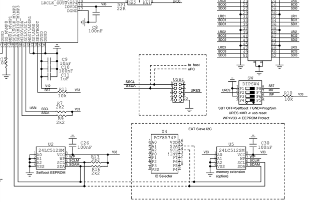
Hello,
The diagram looks fine.
Dave T
I know this has been on here for awhile but wanted to know if you had actually built this board and if you were able to self-boot with the 24LC512SM?
Please log in to reply.