Internal GPIO binary encoding for external logic control
Hi everyone!
I have a question regarding toggle counter output control signal to GPIO binary signal encode. So when multiplexer input #0 is selected, then GPIO DIG2 - DIG1 (bit 1 - bit 0) is binary 000; when selected multiplexer input #1 DIG1-DIG2 is binary 001, #3 binary 010 etc. Please help me with this function realization. Thank you!
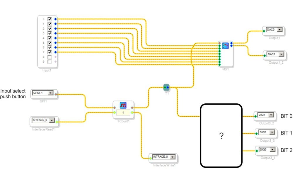
Can I use two (or more) LUTs for binary encoding as on the picture below?
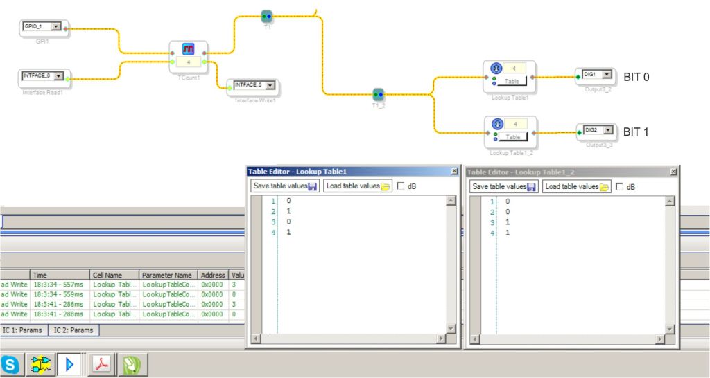
Absolutely! It should work fine.
Bob
Hello oleveger,
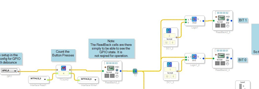
Another way to do it is to use some bit-wise logic cells. Now these are available on the Sigma300/350 parts. You did not mention the processor you are using.
This may be a little more code efficient but I did not compare the memory and MIPS usage. It will probably depend on the number of bits you want to decode.
I have attached the project in case you want to look at it further.
Dave T
Please log in to reply.