ADAU1701 FM MPX stereo encoder problem
So I tried to make an FM stereo encoder. You can see my schematic in the attached picture. I do not have a scope with me right now, but that will probably be my next thing to try if I don't get any hints here.
When listening to it plugged into a transmitter, the problem is that it seems to separate the channels, but they flip back and forth between left and right. It seems like it may be something with the 19khz not being in phase with the 38khz maybe. Another possibility is that FM stereo is DSBSC, so does that I mean I have to notch out the 38khz? I just tried and it didn't seem to make a difference.
Audio Signal Processors
SigmaDSP Audio Processors
adau1701
Hello ogrevorbis,
KJBob Is the guy who has done the most work in this area. Here is a post he did on FM Demodulation.
https://ez.analog.com/message/172159
On this post he basically shows what you need to do:
This post might also be good to read.
https://ez.analog.com/message/19439
So this should give you a direction to head in.
One thing I did notice in your project is that you are doing two things, you are squaring the 19kHz pilot tone and then multiplying it times the difference signal. I don't think this is doing what you expect. Remember that this program runs once every sample period and then waits for the next sample. So it is sample by sample processing. So squaring the level of the 19kHz sample will give you a very high level 19kHz sample. Then multiplying that with the difference of the two audio channels will superimpose (amplitude modulate) the difference signal onto the 19kHz pilot signal but the level will be really low compared to the 19kHz. I guess if you are trying to limit the depth of the modulation this may be important.
Then you are taking this high level signal and multiplying it by 5. Then adding it to the original pilot tone and also the left and right signals. This all does not seem right to me but I am not an RF guy. I will leave this for others to answer you with more detail.
Dave T
Hello,
I've got a few observations which may or may not relate to the left-right switching difficulty:
The screenshot you provided doesn't indicate your sample rate in use. Since the composite signal goes out as far as 53 KHz, your sample rate must be 192K. Otherwise you'll run into serious aliasing, with a result not unlike the sample-by-sample issues which Dave had described.
For the same reason, your analog DAC reconstruction filters can't be like the standard ones on the ADAU1701 eval board -- instead they need to pass signal up to 53 KHz.
Your baseband filter should cut off at 15 KHz to keep the composite bandwidth within limits.
I see what you're doing with squaring the 19 KHz pilot tone to derive your 38 KHz subcarrier -- you're using the trig identity (sin(x))^2 = 0.5*(1 - cos(2x)). This worked fine on my demodulator.
Multiplying the (L-R) signal by the 38 KHz LO is by definition suppressed carrier -- so a 38 KHz notch shouldn't be necessary. You may wish to place a DC block filter between the L-R subtraction and the multiplier, to prevent any DC there from generating a 38 KHz spur.
Is your pilot strong enough (the spec calls for 8-10% modulation, but your pot shows -50 dB)?
Have you tried testing with different FM receivers -- do they all respond the same? How often do the channels flip?
Best regards,
Bob
Thanks both of you for the help!
I have fixed this problem. I added a low pass filter between the 19 khz generator and the volume pot. Now the signal stays on one side The separation is terrible though and I can only detect the difference if I turn the balance all the way to one side.
I am still posting what I was going to earlier because I would still like some input:
Dave: I had a look at all those links, but they seem to be following the same principle as me. I just have a lot more additional blocks.
Bob:
Yes, the sample rate is set to 192 khz and the filter on the output of the board has been removed. This was the case through all the experiments.
I can tweak the baseband filter back down to 15 khz, but it seems to make no difference. I just had it at 16 khz for a little more treble.
I will try adding another DC block.
Yeah, that volume pot is kind of weird. It says -50dB, but I looked at it on a spectrum analyzer and it was much higher and the receiver would start making a tone if I raised it higher. Something I should check though is lowering the volume of my computer a lot and then increasing the pilot because maybe I am just confusing it with the computer volume.
I have tested on two different receivers with the same results. The flipping occurs about once every 2-5 seconds and it varies.
Congrats on your progress. It appears that the phase lag added by the new 19 KHz filter brought your resulting composite signal more into line with its official definition -- the Wikipedia article I have found has both frequencies as sine tones, compared to the squarer producing a minus cosine. This phase error could very well have confused the subsequent decoding. I'm guessing that any receiver you tried is a modern "system on chip" variety. An older radio might have used a LM1800 PLL MPX decoder. A real old radio derived the 38K with a diode "squarer" and a LC tank (and back in those days I rode a Parasaurolophus). Either of these might have given different results.
To achieve good stereo separation, the receiver must recover the (L+R) and (L-R) signals in precise amplitude and phase so they add and subtract exactly. By extension, this requires that your MPX modulator generate them exactly according to standard. For example, a ten percent error in the baseband vs. subcarrier strength is hardly noticeable in dB terms, but would already impose a 20 dB limit on your separation. Phase errors likely do similar damage although the math is more complex. To improve separation, perhaps you could:
Tweak your amplitude ratio of baseband and modulated signals for best separation.
Try different phase shifts -- for example, if the 19 KHz filter you inserted is second-order, try a first-order filter instead -- or perhaps test an allpass instead of a lowpass. Or whatever.
jimwoodElectrojim is the best FM transmitter expert I know of on this board -- I'm curious if he could offer any suggestions.
Best regards,
Bob
Would there be a more elegant way to make sure both the 19 khz and 38 khz have the same phase? Maybe a PLL, but I've never seen this type of PLL. What I really mean is something that is a better alternative to multiplying the 19 by itself. I can try messing with the filters to change the phase, but if I am understanding the problem correctly, then this will probably never completely fix the problem. As I understand it, I need these two completely in phase.
I had a look at some more of the blocks I haven't used in Sigma yet (haven't been using it for very long). I couldn't find any type of sine generator that would allow me to lock the phase to anything else. Maybe you know how to do this?
Appreciate the help,
Paul
KJBob, you are far too kind, and definitely not in agreement with a certain FCC field inspector, back when I was in high school. My 50-watt AM broadcast-band transmitter blacked-out every TV in a 4-block radius.
An audio processor/stereo-gen that I put together in Sigma needed only an amplitude tweaker in the L-R subcarrier path, as it was combined with the L+R monaural component. However, an all-pass in the 19kHz pilot path allowed subtle adjustment of its phase so that the overall stereo separation, measured on an actual laboratory-grade decoder, was just about 60dB out to 10kHz. There were additional shenanigans in the (L+R)+(L-R) to increase ‘perceived loudness’ before the pilot was injected, which accounted for at least part of the need to adjust pilot-to-subcarrier phase, but this adjustment did then allow even some fudging for shortcomings in a simple analog low-pass filter following digital-to-analog conversion. The final performance was judged ‘certainly good enough,’ but if you are wanting to beat a Guinness separation record, try a first-order all-pass of just the L-R. It well may improve top-end separation.
Paul, with respect to your last post, above, I can think of no better way to guarantee the phase coherence between the pilot and the suppressed subcarrier than by deriving the latter from the former. Doubling (through self-multiplication) of the 19k is the easiest and, probably the most stable, way to ensure a proper phase relationship. You will need an all-pass, or some other way to set this relationship, but once you do it will be good forever and ever, amen.
And since the subcarrier is suppressed, it's often difficult to get a visual between the two signals. Might I suggest that you do an extra D-to-A conversion and create a temporary output port for the 38kHz 'doubled pilot' signal? Then you can see them as separate traces on your scope. You might have introduced too much 'phase adjustment' with your all-pass or whatever, and actually have several 'rotations' between the two. This is of no consequence, of course, since nobody's going anywhere, but just to keep things neat and clean, and to have an idea of how much phase displacement you're working with, keep the two signals as close to the same origin as possible.
Jim,
Thanks so much for helping us with your insight and troubleshooting!. Generally, dragging in an extra DAC to examine intermediate signals can be quite helpful in many applications. Though this DAC inverts the signal and adds delays, these cancel with those from the functional DAC(s). And although DSP works with discrete and quantized samples, SigmaDSP does surprisingly well adapting "analog" functions to this realm. As long as the sample rate is high enough.
50 watts!!! I played around with a mini AM transmitter (running a 12AT7 of all things) in my younger days, but you've got me beat. Many years ago, Electronics Illustrated ran an article about two high-schoolers broadcasting just below 5 MHz with a modified amateur transmitter. They played harmonica music and cracked jokes -- it must have been fun listening! Not like the over-commercialized fare we're stuck with today.
Best regards,
Bob
Hello,
Against all rules I used 2 VCO's to generate the 19 kHz pilot and 38 kHz subcarrier...
No channel flipping however and great channel separation. Works like a charm!
Best Regards, ODJ
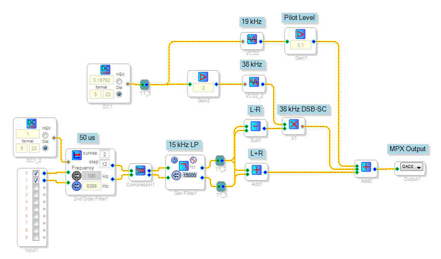
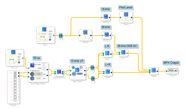
Happy to hear it works! I had once played with a project which added harmonics to a fundamental sine wave to make various waveforms. It worked fine using a similar method. What each VCO does is add a number proportional to its "voltage" input at each sample interval to the driving input of a sine lookup table. Double the input, double the frequency -- as long as the DSP performs its math perfectly, the two frequencies maintain their phase relationship. And why shouldn't the math continue accurate over any finite interval? It's a computer, after all. Yet I still feel it's a bit scary. Possibly my general mistrust of computers.
Best regards,
Bob
Could you please tell me how to change the 50usd pre-emphasis to 75us ?
This can be done by changing the frequency from 6366 Hz to 4244 Hz.
Thank you
Tried this design and can only get 20dB of channel separation between channels. I was able to get 37db separation from a cheep $10 transmitter and I was hoping to get much better with a DSP.
I also tried to vary the reference +/- 10Hz via aux ADC to see if that made a difference but none could be detected .
Tried chaining the gain via AUX ADC of the modulated channel - still 20dB was best I can get.
Want to try changing phase of the reference but do not know how.
For anyone else interested in this concept.:
I made more tests with an adjustable delay in the L+R channel and for a delay of 4 samples a was able to get about 35dB separation at 1Khz test input. .... But the separation is very poor and high and low frequencies. This is good enough to play around with but not good for serious work. I plan to use the DSP as a limiter / filter pre emphasis stage for an analog MPX . I think that will be a better use of the DSP.
The DAC output filter can have a huge impact on the MPX signal if the cut-off frequency is too low...
Make sure the amplitude response is flat up to 100 kHz or so.
You can try removing all caps to ground at the output to experience the difference.
Channel separation can be way better than 35dB.
For anyone interested,
This simple Stereo Encoder project has evolved into a complete FM Broadcast Processor with MPX and RDS Encoder using an ADAU1467....
All information can be found in the project file.
Have fun!
Orreban V1.0.dspproj.zip
Please log in to reply.