Can two modules be attached to ADAU1701?
I am new to this.
This is what I ordered:
http://store3.sure-electronics.com/adau1701-audio-digital-signal-processor-kernel-board
It has the dsp itself and the extension that has 2 rca inputs and 3 rca outputs.
Could I just plug two those extensions to the dsp or what would be the smartest(and most cost effective) way to achieve at least 6 rca outputs?
Audio Signal Processors
more
output
rca
SigmaDSP Audio Processors
adau1701
Show More
Hello,
The ADAU1701 includes two ADCs (inputs) and four DACs (outputs). Thus to handle six outputs, you need two of the kernel modules. Likely this is still lower in cost than a more capable DSP and separate codec (ADC and DAC) chips, especially if you wish to purchase modules instead of designing your own board. You also need their programmer board to connect to SigmaStudio and program each module's EPROM for self-contained operation.
Best regards,
Bob
Ok so how I can get the 4 outputs because the module onlyhas 3x rca + 1x 3,5mm output. If i want to get 4x rca out?
Also I found a "MadBit DSP5" wich is based on the ADAU1701 and it has 5 output channels. How is that if it has only 4 outputs?
Hello mrazx,
I think you will have to ask the MadBit people how they are doing that trick. The DSP has four outputs. They may be bypassing some of the signals in analog or getting a difference?
Dave T
Since each module has three RCA jacks, when you use two of them you can get six RCA outputs as well as one more output from each DSP which I don't know what Sure did with. I can't find any module schematic on SureDSP's website but hopefully such is available to their customers. The schematic along with the ADAU1701 data sheet can help you navigate issues such as this. Even though you're aiming to use pre-made modules, the more you understand their workings, the better your results will be.
Best regards,
Bob
It has ADAU1701 and a PCM1754 for subwoofer output connected with I2S. Do you have any idea or schematic how is that done?
Hello,
You can get your ins and outs directly from the two 20-pin connectors on the kernel board. Perhaps the easiest way to access these pins is to cut a ready-made 20 pin F-F ribbon cable in half. Then pull apart the cut ends for wiring to your RCA jacks. ,
Edit: I had overlooked the numerous passive components that exist on the expansion module. These could very well be the external parts needed by the ADAU1701's ADCs and DACs -- in which case the above suggestion won't work..
Re your other question about connecting an external codec via I2S -- this is only practical if you're willing and able to design/engineer your own PCB with the ADAU1701 and PCM1754 chips plus their support components. This of course is a lot more difficult than applying an off-the-shelf module.
Best regards,
Bob
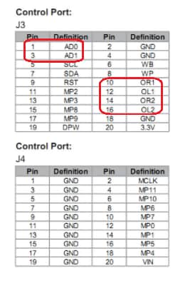
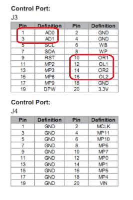
Is there any way of getting more than 4x outputs? If i remember correctly the chip/board has some kind of digital output also. Can that be converted to analog(with or without additional modules/chips) and thus to rca output?
I know that there is the possibility of using two of those suredsp boards, so i'g have 8x outputs, but i am thinking now about the options about solving this with just one board.
Hello mrazx,
Yes, the part has a serial port that can be setup as an I2S port for stereo output or can be setup for a TDM4 or TDM8 output to output 4 or 8 channels of audio. This would need to be hooked up to an external multichannel DAC.
You could also send four channels of data to a second part and use those 4 outputs to give you 8 channels but this is usually not a great way to do this.
Oh, I should also mention that the serial port uses several multifunction pins and those pins might be used on this PCB. So getting access to them to use for a serial port might require some modifications on the PCB. I support the part and I do not know the Sure DSP board very well.
It sounds like you are designing a crossover that is a stereo four-way crossover? Then I suggest you run the part in mono and use two of them. This way the audio will not have to leave the part. The only tricky thing to do will be to link up the volume controls. There are a number of ways to do that.
Dave T
I would like to have 4x outputs for tweeters and midranges, 2x each, and one for subwoofer. But I guess that it is not possible with one board due to 4ch output. Because then the subwoofer channels has to be on either tweeter or mid output crossover in the program. I cannot magically create own output in sigmastudio for subwoofer(?).
Hello,
You can use three boards. You take your stereo signal and run it into one 1701 board #1. This DSP will have a two-way crossover in it to separate out the low frequencies for the woofer and send the rest of it out two outputs. It will then take the stereo subwoofer signal and sum it into mono and send it out the third output. This leaves you one spare on this board. You can also do all the volume controls and muting on this DSP #1.
Then you connect the left and right outputs from board #1 into two separate 1701 boards. 1701 #2 and #3.
These two are exactly the same program to take the audio in and run it into a crossover and produce your two tweeter and two midrange speaker outputs on each DSP. 1701 # 2 will be the left audio and #3 will be the right audio.
I think that will solve your issues.
Dave T
That seems pretty difficult. I could use one board for mids and tweeters and one board for subwoofer, because I have 6 outputs on my radio.
Though I guess if I use more than one board I must program every board separatey? I cannot program a board 2 via board 1?
Hello marzx,
Then I was confused when you said:
I would like to have 4x outputs for tweeters and midranges, 2x each, and one for subwoofer
I read that to be per channel.
So if you simply have a three way crossover then is the subwoofer mono or stereo? Because if you have to sum the sub signal then they both must be in the same DSP.
So now I am even more confused? Six outputs on your radio? Are you taking in signals that are already split out be a different crossover?
So let me stick to SigmsDSP questions and SigmaStudio questions.
You can address more than one part at a time with SigmaStudio. If you read the datasheet about the I2C section you will see there are two address pins where you can set the address of the SigmaDSP. Then in SigmaStudio on the config page you can drop in more than one SigmaDSP cell and assign them to different addresses on the I2C bus.
Now comes one of the tricky parts. You need to jumper the I2C bus between the two boards so that it will communicate with the two boards. You need to do this so that you can easily disconnect it.
So when you compile/link/download the compiler will write the program to both parts one at a time. So you will be able to communicate with both DSPs over one connection.
You will have to see if this Sure PCB is able to set the address of the DSP. It might be simple tied to ground in a way that you cannot change it.
The next tricky part comes when you try to program the EEPROM for selfboot. For that you CANNOT have the serial ports connected together. You must connect to them one at a time and then program each EEPROM one at a time.
Then when you actually power up the boards when they are set to selfboot then again, you cannot have the I2C bus connected between the two boards. This is because the two EEPROM have to have the same address and each DSP does know about the other one so they will both be trying to boot up from an EEPROM with the same address at the same time. This will not work...
Dave T
Please log in to reply.