ADAU1452 I / O Inquiry
I have a question about GPIO of ADAU1452.
One of the customers wants to use the ADAU1452 with self-boot function, audio input 4ch, audio output 4ch, GPIO 14ch (MP0 ~ MP13).
In the datasheet and EVAL B / D circuit, self-boot and MP0 ~ MP3 use the same pin and some other pins are assigned to Audio CLK, Is there a way to implement the above requirement?
Thank you
Audio Signal Processors
adau1452
SigmaDSP Audio Processors
Hello Andrew,
You said four channels of audio but I was not certain if you mean four serial ports or four channels of audio using I2S which will consume two serial ports? If you use TDM-4 then you would use only one serial port.
Either way, you will need to use at least two of the GPIO that is multiplexed with two of the LRCLK pins for the serial data. So you would not have 14 GPIO. You will need to migrate up to our newer parts that have much more GPIO.
The ADAU1463 or the ADAU1467 (one has more memory then the other, otherwise they are the same) These parts have up to 26 GPIO pins so you should have no trouble finding 14 pins available. These parts are pretty much the same. core so they have the same processing power but the difference is in the memory available and the number of pins so there are more AUXADCs and more GPIO and more serial ports. Some of these functions are multiplexed but I think it will be fine for your application.
Dave T
Andrew,
Unfortunately, there is no way to use all 14 GPIO pins and self-boot the ADAU1452 since the functions of the pins are multiplexed. You can come close, however, depending on the timing of your I/O. If all of your inputs and outputs share the same LRCLK rate, then you can use up to 13 of the 14 GPIO pins after self-boot. The master-port pins must communicate with the EEPROM, but you can use them as GPIO after self-boot completes. If you have a firm requirement of 14 GPIO pins or more, I recommend that you look at the ADAU1463. That part is code-compatible with the ADAU1452, but it is in an 88-pin package rather than 72-pin and offers more serial data lines, more GPIO, and more memory.
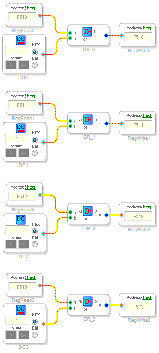
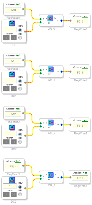
To re-purpose the self-boot pins as GPIO after self-boot, you can manually write to the pin configuration registers from within your program using the Basic DSP -> DSP Functions -> Register Read and Basic DSP -> DSP Functions -> Register Write block. The master port pin are multiplexed with MP0 through MP3. The GPIO function of muxed pins is enabled by the MP_ENABLE bit (the LSB) in the MPx_MODE registers. MP0 through MP3 are at addresses 0xF510 through 0xF513. The safest way to toggle this bit without corrupting other settings in those registers that you may have made in the GUI register window is to read the current value and OR it with the LSB as follows:
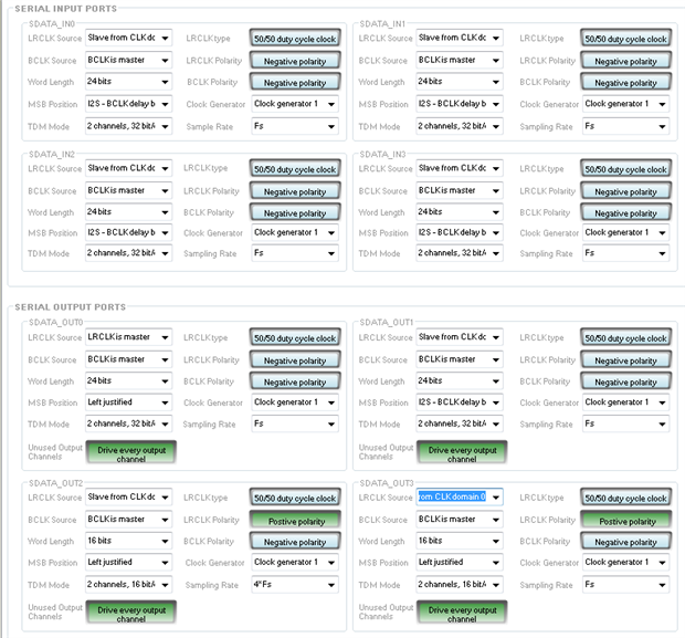
If all of the input LRCLKs are the same, configure them to slave to the one real pin in use. The same applies on the output side. Configure them to slave to the one real pin in use. For this example, I am showing the the two pins the are physically connected as LRCLK_IN0 (as a slave) and LRCLK_OUT0 (as a master). Either could reverse direction. Note that the BCLK pins are not multiplexed, so you can configure them to suit your system.
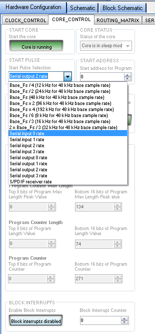
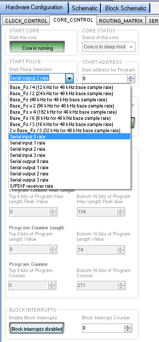
This will free up the LRCLK pins that are multiplexed. Including the master port pins, you now have 12 of the 14 possible GPIO pins free after the self-boot process completes. To get the 13th, you must slave the core rate to one of the serial ports. Unfortunately, there is no way to directly slave the LRCLK of the input ports to any of the output port (or vise versa). However, you can slave the core frame to either an input or output serial port LRCLK then slave any serial port LRCLK to the core by setting it as a master. Keeping the above configuration, on the CORE CONTROL tab, set the START_PULSE to sync to either the LRCLK_IN0 (shown below) or LRCLK_OUT0.
As I mentioned at the start, you would get all of the features that you are looking for with the ADAU1463. However, this will give you self boot plus 13 of the 14 GPIO pins.
Ken

Thank you Mr. thib
Thank you mr M
I will recommend to my customers use adau1462.
Hello Andrew,
The ADAU1462 is not the correct part. It is the 1463.
Thanks,
Dave T
Please log in to reply.