ADAU-1452 serial out to AD9957 Blackfin input
I need to format I/Q data from the ADAU-1452 as two 16-bit serial inputs to the AD9957 QDUC operating in "Blackfin Interface (BFI)" mode. The I and Q bits from the ADAU-1452 need to arrive at the AD9957 input on the same serial clock edge. Can someone guide me as to how I should configure the output port(s) on the ADAU-1452 in Sigma Studio?
Quadrature Digital Up Converters (QDUC)
High Speed D/A Converters =30MSPS
ad9957
First, you should note that the ADAU1452 runs more than an order of magnitude slower than the potential speed of the AD9957. The maximum serial bit clock of the ADAU1452 is 24.576 MHz, and that of the AD9957 (PDCLK) is 250 MHz. If this meets your bandwidth specification, the interface would be done as follows.
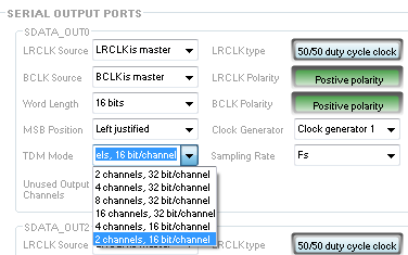
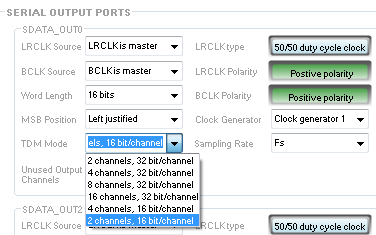
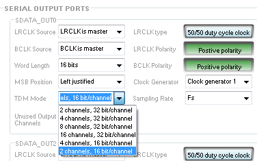
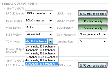
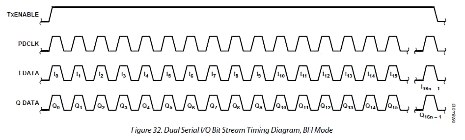
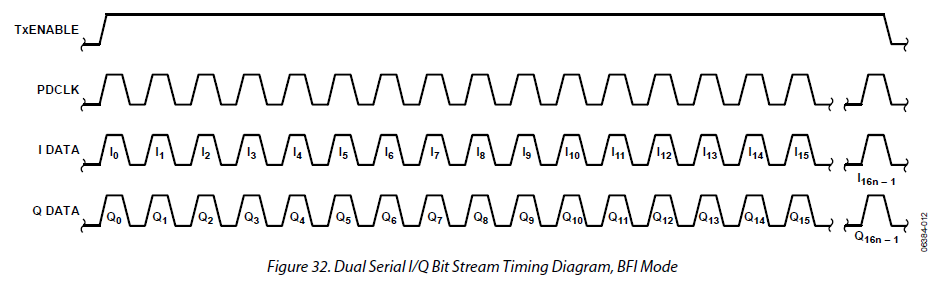
The BFI input on the AD9957 requires two serial data streams. Therefore, you would need to use two serial output ports on the ADAU1452. For this example, I will use output port 0 for I and output port 1 for Q. The AD9957 clocks the data in beginning on the rising edge of the frame sync (LRCLK_OUT). This would correspond to left aligned audio data beginning on a rising edge. BCLK_OUT0 connects to PDCLK and LRCLK_OUT0 connects to TxENABLE. SDATA_OUT0 connects to the I input and SDATA_OUT1 connects to the Q input. Set the framing as above, and set the word width to 16 bits as follows:
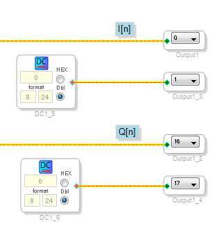
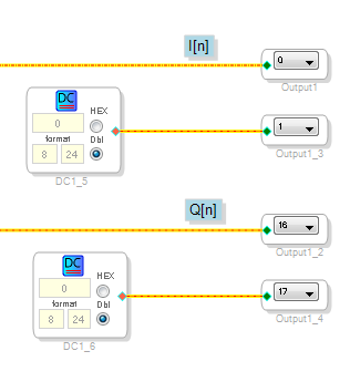
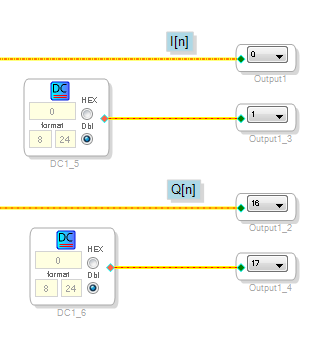
Note that data is ignored when the LRCLK/TxENABLE line is low, so the even channels from the ADAU1452 should be filled with zeros. In the schematic, the flow would look like this:
The data should be formatted as 2's complement such that it ranges from +1 to -1 in 8.24 format. You can check this with a DSP Readback block. The top 7 and bottom 9 bits will be truncated.
I hope this helps. Please let me know if you have any other questions.
Ken
Thanks for your response, Ken. That is the direction I instinctively thought would be correct, but I appreciate your confirming it before I spend too much time on it. All that flexibility of input and output serial data formats is dizzying!
My pleasure. The serial ports are very flexible, but it can be overwhelming. Don’t hesitate to follow up if you’re having trouble.
Good luck,
Ken
Brian,
Since I sent my answer, I've been wondering if I could find a way to get some extra bandwidth for you out of the ADAU1452. Sure enough, we can. It's sort of an odd trick that is pretty specific to your application, but we can run the DSP up to 768 kHz. Here's how:
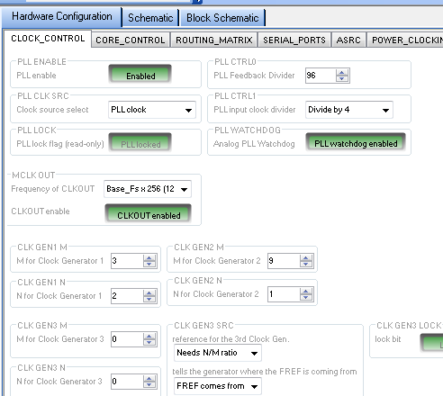
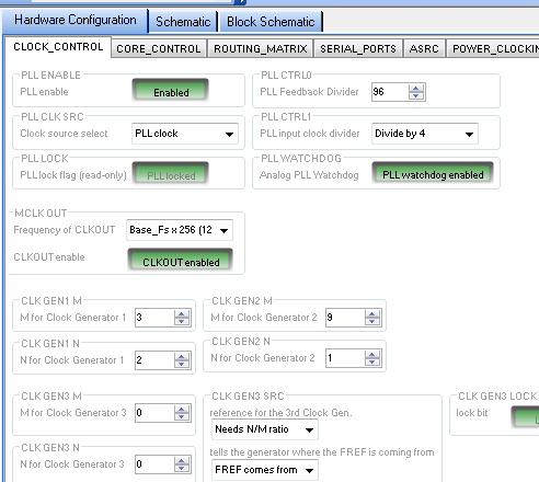
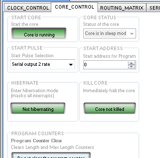
First, set the core to run at its fastest native rate, which is 192 kHz. The settings below are based on a 12.288 MHz crystal. Note that the N/M for CLKGEN1 is 2/3.
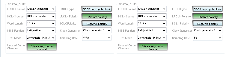
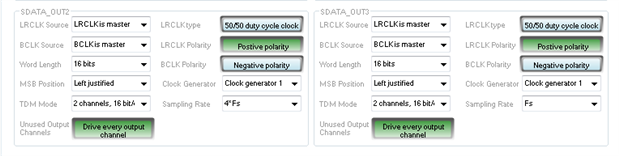
Next, configure the serial ports with a slight variation from my previous post:
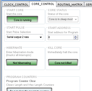
I happen to be using output ports 2 and 3 this time, but the important point is that the sampling rate is now set to 4*Fs instead of Fs. Normally, this would not be very useful. The effect would be repeating each sample value four times. However, there is one additional setting that must also change:
The STARTPULSE setting sets the trigger (pseudo-interrupt) that signals that the core should begin computing the next sample frame. By default, it is set to the same clock generator as the core (Fs from CLKGEN1). However, it's a useful feature of the architecture. It can be used, for example, to slave to an incoming S/PDIF signalor or to have the DSP operate as a true clock slave to an external serial input.
In this case, we are setting the serial port in clock master mode.running at 4x the core rate, and driving the STARTPULSE to that serial port. This has the effect of restarting each sample calculation at 4x the core rate of 192 kHz or 768 kHz. In normal I2S mode, this would violate the maximum rate of the serial port (768 ksamples/sec * 64 bits/sample frame = 49.152 MHz. However, you only need 16-bit data, and you are using a mode with only 32-bits/sample frame. This works out to 24.576 MHz, which is within the SPORT timing spec. Note that this is true even on SPORTS 2 and 3 that nominally support only 8 channels instead of 16.
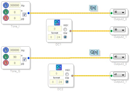
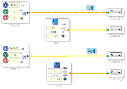
This schematic...
...shows on my scope exactly what I would expect: two 16-bit, 0 dBFS, 300 kHz tones that are 90 degrees out of phase. The disadvantage of this hack is that you end up with 1/16th as many instructions per sample as you would have at 48 kHz. The tradeoff may be worthwhile if you are driving a DAC with an I/Q input, though. I hope you find this helpful.
Best regards,
Ken
Ken,
Thanks for continuing to add value to your original post. I truly
appreciate your diligence, in addition to appreciating the fact that
Sigma Studio brings DSP to "the rest of us."
I'm going to jump on the bench and work this up tomorrow.
Brian
On 12/13/2017 at 4:59 PM, "Ken.M" wrote: *
a body { font-family:Helvetica, Arial,
sans-serif; }
EngineerZone
Re: ADAU-1452 serial out to AD9957 Blackfin input
reply from Ken.M in _SigmaDSP Processors and SigmaStudio Development
Tool_ - View the full discussion
Ken,
We can't sacrifice so many instructions, so this approach won't work
in our application.
What does the "Unpack 16bit Audio" block do? It sounds like just
what we need. There is no documentation.
Brian
Ben,
I've just noticed on page 52 of the ADAU1452 datasheet that LRCLK and
BCLK can be slaved to clock domains 0 to 3. It looks like the BCLK_SRC
register allows the serial output port to be clocked by an external
clock arriving on a BCLK_IN or BCLK_OUT line.
Is this the feature I need to have the serial date clocked onto the
output port by the AD9957 PDCLK?
Hello Brian,
I will answer your question about the "unpack 16 bit audio" cells.
The UNPACK is designed to take in a 32 bit audio word and split it into two 16 bit audio words.
The PACK is designed to take in two 16 bit audio words and pack them into one 32 bit word.
The data in the core is all 32 bit so you can move this data around inside of the core quite easily.
However, the problem come in when you go into and out of the core. The standard hardware path goes through clippers and saturators and moves the sign bit to the proper place. so you have to bypass all that. Fortunately, the designers made this possible and it is easy to do in SigmaStudio.
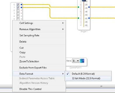
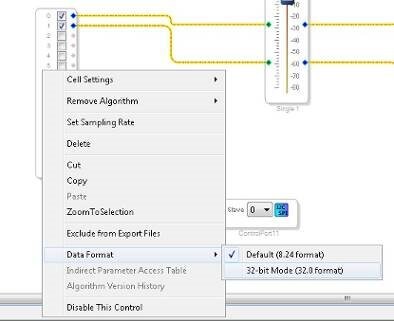
For this to work you would need to change the input and output ports to the 32-bit mode.
Right click on the input or output cell and select "Data Format". Then select the 32 bit mode.
For the moment, I will leave it to Ken to respond to your other question.
Dave T
Brian,
My second post was just intended to provide extra bandwidth if you needed it. I wanted to show that you could trade off instruction count for bandwidth if necessary.
The issue with using the 16-bit packing blocks is that the modulator is expecting two separate serial streams. Each stream must be left aligned and zero padded, and the quadrature data must be clocked in simultaneously as you state in your original question. The packing/unpacking blocks will place both channels on a single pin with the data interleaved.
Regarding formatting the serial data, please refer to my original post. That will do what you need without any additional instructions if you don't need more than the documented sample rates. The answer to your follow up question is "yes." As I said:
BCLK_OUT0 --> PDCLK
LRCLK_OUT0 --> TxENABLE
SDATA_OUT0 --> SPORT I-DATA (I input)
SDATA_OUT1 --> SPORT Q-DATA (Q input)
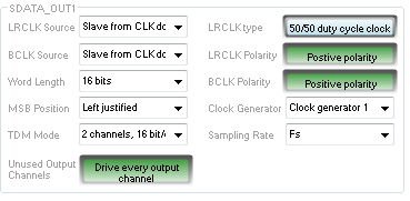
I apologize. I showed only the configuration for serial output port 0 (the first three pins above but not the fourth). Serial port 0 should be:
The bit clock (BCLK_OUT1) and framing clock (LRCLK_OUT1) for serial output port 1 must be slaved internally and the pins left unconnected. The configuration that will produce the correct output for SDATA_OUT1 is as follows (The first two lines are cut off in the image):
LRCLK Source: Slave from clock domain 0
BCLK Source: Slave from clock domain 0
This configuration with this signal flow will generate a pattern with only 16 bits clocks while the LRCLK is high as required:
The SigmaDSP will clock out zeros while LRCLK_OUT0/TxENABLE is low. I'm a little confused as to why the PDCLK rising edge falls while the data is transitioning, but I suspect that is an oversight and the clock should be delayed by a quarter cycle.
Best regards,
Ken
Please log in to reply.