ADAU 1701: lost I2C connection
Hi at all,
in my application the ADAU 1701 is working as a slave with a uC. The first prototype worked properly for some days at my desk. Then some connection problems started. I had to reconnect many times until the DSP worked again. Now he is completely dead. When I looked at the I2C bus I noticed the following:
No debugger conected: SDA, SCL high through the pullups, so everything ok.
With debugger (official AD UDBi): SDA, SCL high but after the first connection the SCL line remaind low. (I tried the connection with the official ADAU1701 eval board were the debugger works still very well.)
In the beginning I could see a first telegramm. That became to just 3 or 4 level changes and now.... nothing.
I tried to disconnect the uC to have just the DSP and the debugger at the bus but that changed nothing.
Is there any possibility to check if the DSP is still allive? Or to make sure that the I2C unit has died?
Thanks in advance!
Audio Signal Processors
i2c
SigmaDSP Audio Processors
adau1701
Hello turborierer,
It would be very unusual for the I2C port to have a failure. It is a slave port so it only reads the data. Since the voltage levels are handled by pull-up resistors it does not have to drive the pin high, only sink current to ground. So it would be very unlikely for this to fail.
Could the uC be trying to communicate with the DSP at the same time that the USBi is trying to communicate? The USBi is not able to handle a multi-master condition and does not check for collisions. So may have been waiting for an ACK that it will never get.
I do see you tried to remove the uC.
So can you send over your schematic. I have some other things I would like to check and it is faster by looking at a schematic. (Hardware schematic)
Dave T
Hello Dave,
thanks for your comment. There is definitly no communication from the uC at the same time because I physicaly disconnected the pins.
What is really strange that the SCL line is first high and then after the first attempt to start the connection it remains pulled low.
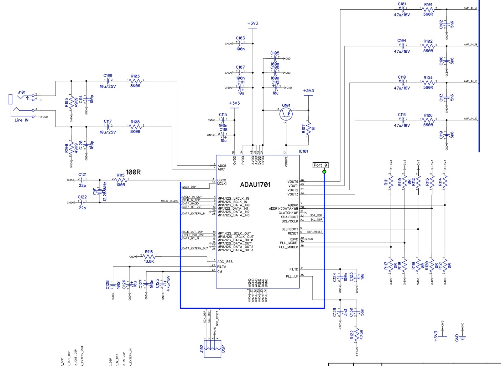
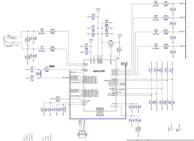
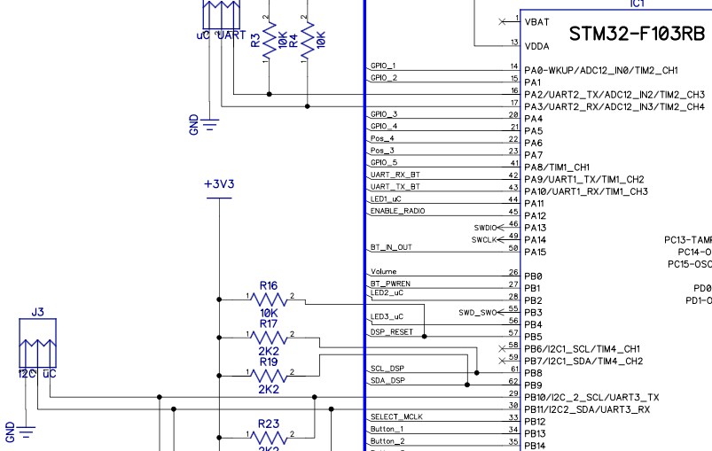
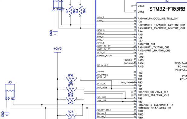
Please see the part of my schematic.
Thanks in advance!
turborierer
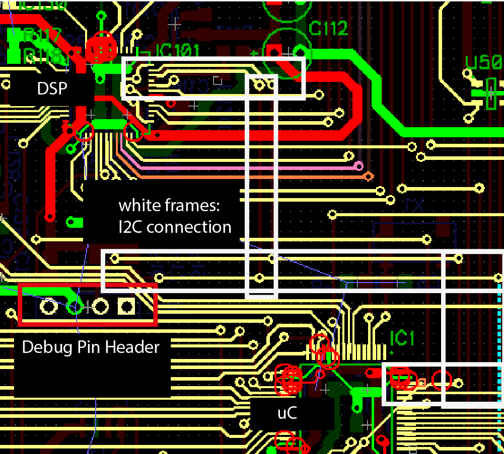
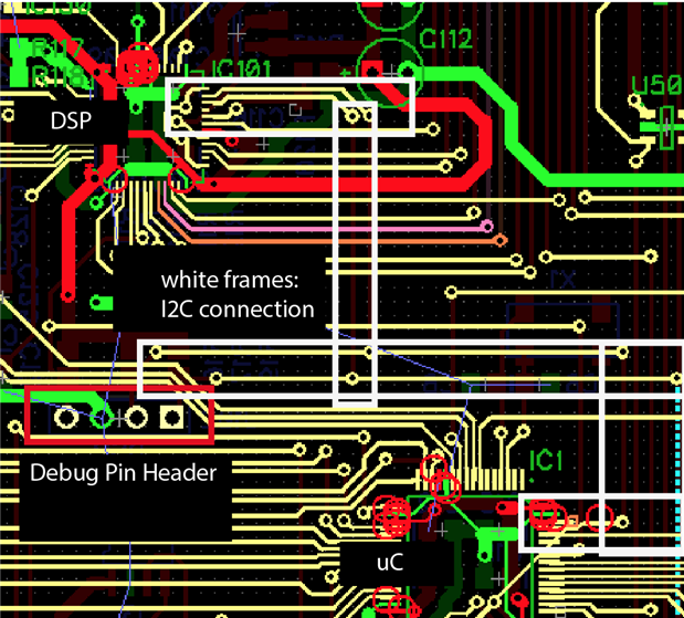
Hello turborierer,
I think I see the problem. You have the crystal going off somewhere else and then there is an MCLK signal coming back from somewhere. Conditions have to be just right for a crystal to oscillate reliably. You have to watch for stray capacitance and keep leads short etc. You cannot run one side of the crystal to anything but the MCLKI pin and the leads must be short so there is little stray capacitance.
Without MCLK the part will not function and only a few registers can be read or written to. Actually, I think in this part none of the registers can be written to without MCLK present.
The Cypress chip we use on the USBi does sometimes hold the bus low when something is not working with the I2C communications. I think what is happening is that the transmission is not completed, the USBi did not receive an ACK from the part and so it sits there and does not release the line. I have seen this before and is not a worry for me. You have tested the USBi on the evaluation board and it functions fine so the problem is not with the interface and I have never seen the I2C port fail on a part so we have to look elsewhere in the system for the answer.
Step 1, make sure you have valid MCLK and that the PLL had time to lock before trying to communicate with the part.
One other question, do you have the selfboot pin set high? If you do then the part will change the I2C port to master mode and it will be trying to bootup from an EEPROM. You have to wait for the part to fully bootup before trying to communicate with it.
Dave T
Hello Dave,
yes that was it. One beer for you!!! Days of frustration just found their end.
There was a SW bug that prevented the radio to boot correctly. No radio, no MCLK from the radio. When I switched to the crystal I got immediately a connection to the DSP.
And yes, your right the stroy with a switchable clock and long leads is a pretty bad idea. The next question is how could I deal with a radio that provides a MCLK as master and a DSP running at its own crystal? Does the DSP some kind of resamping or will I have dropouts after a perioud of time?
The problem is, that beside the radio I have some use cases (Line, Bluetooth) where I don't have the MCLK from the radio. That was the reason for the switch.
Thanks a lot!!!!
Kilian
Hello Kilian,
This is a tough problem when you have different sources all running at different rates that are not synchronized. This part, the 1701, does not have any sample rate converters so you have to feed it signals that are correclated with the MCLK that is being fed to the unit.
Assuming you cannot change the part to the ADAU1452 which does have sample rate converters and would handle this application quite well, then you will have to deal with this using the system controller.
When you switch from one source to another you will have to change all the clocks, the MCLK, BCLK and LRCLK so that they are correlated to each other. Assuming you are in the MCLK = 256x fs mode, then you should not have to perform a full reset and reprogram. I think just changing to a new MCLK would work OK. You have the PLL to deal with and if it is too drastic of a change then the PLL may not lock fast enough.
You will have to mute the audio when doing these switchovers.
So assuming you have all the different MCLK sources going to the controller, then it can send the correct MCLK to the DSP. It also need to send the correct BCLK and LRCLK for that device.
If all these sources were running off of the same Master Clock then all this would not be required. But, in your case I don't think this is possible.
Dave T
This question has been assumed as answered either offline via email or with a multi-part answer. This question has now been closed out. If you have an inquiry related to this topic please post a new question in the applicable product forum.
Thank you,
EZ Admin
Please log in to reply.