ADAU1452 Clock Generator 3 input restriction
Hello,
I tried 750Hz pulse as input to ClockGenerator3 and want to generate FS48kHz signal as output.
Does this requirement setting contain a problem?
Is there any restrict frequency range as ClockGenerator3 input?
Audio Signal Processors
adau1452
SigmaDSP Audio Processors
Hello takumi3952,
I know that the datasheet has this information well hidden but it is there. It is in the register details section and in the Generator 3 input reference generator register.
There you will see that it takes the input signal from the external pin and multiplies it by the value in the "N" register then divides it by 1024. The "M" register is ignored. The "N" register defaults to "0" so that is probably why you saw no output.
Since there are only multipliers and dividers there are no low frequency limits but there will be a limit as to how high. I am not 100% certain but it is probably around 200kHz.
Then remember that you can divide or multiply this further by using the sampling rate setting on the serial ports. So this is why I am not certain how high you can push the output.
Dave T
Hello Dave,
Thanks for your reply.
That is, there is no restriction on the lower limit of the input.
There is no problem with the setting of the output 48KHz with the input 750 Hz.
Is my understanding correct?
Thanks and Regards,
Hello takumi3952,
So the formula would be this:
xN/1024= f, With x = the frequency of the signal on the pin and f is the output. N, is the "N" value register setting.
So solving for N I get:
N= 1024f/x
So for an output frequency of 48,000 and an input frequency on the pin of 750 this would be the calculation for N
N=[1024(48,000)]/750 = 65536
( which is interestingly equal to 0x10000) Nice number!
So set N= to 65536 and you will get exactly 48kHz out of the clock Generator. They don't always divide so evenly but in this case it does.
Dave T
Hello Takumi3952,
I wrote this response just before leaving work at the end of the day. Then driving home I had a realization and unfortunately I was correct. The "N" register for clock generator 3 is a 16 bit wide register. It cannot hold a 0x10000. The largest it will hold is 0xFFFF which is 65535.
So using this multiplier you will get a clock out of 47.999kHz. So it will not quite do 48kHz but it is really close. I would think this would be OK for your application but I do not know the details.
Dave T
Hello Dave,
Thanks for your reply.
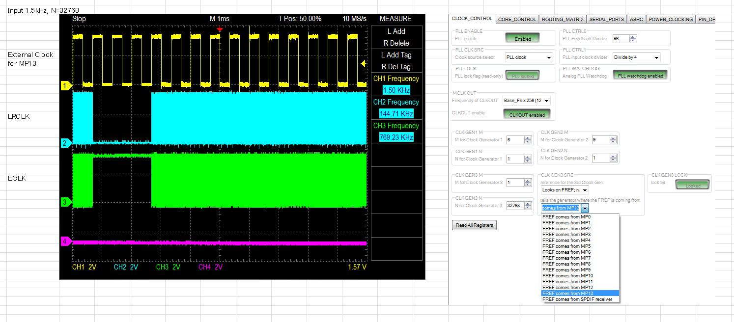
Can you see the attached picture?
Input 1500Hz, N = 32768
I expect 48kHz clock should be generated.
Although,generated clock is defferent from expected.
What is incomplete in the setting?
Thanks and Regards,
Hello takumi3952,
I have consulted with a design engineer and we looked into the design and ran simulations to determine the limitations of the external reference for the Clock Generator 3.
There is an internal counter that counts the number of PLL output pulses between the external reference edges. I would expect it is the rising edge. This counter is a 16 bit counter. The designers probably never expected customers to use such a low frequency. So for a nominal PLL output frequency of 294.912 this counter will overflow with a reference input of 4.5kHz.
So a reference frequency of less than 4.5kHz will not yield expected results and probably will not lock at all.
In addition, I would not recommend a nominal reference that is close to this number because any jitter will cause the counter to overflow. Therefore, something closer to 5kHz minimum reference frequency is more likely. I would have to calculate jitter and have that be part of the specification that the jitter distribution cannot dip below 4.5kHz or lock will be lost.
I think you were able to achieve some sort of lock because the frequency you were looking to generate was a multiple of the PLL output clock rate. It was aliasing I guess you could say.
So now we both know what the constraints need to be for selecting the external reference frequency.
Dave T
Hello Dave,
Thank you very much.
This information is very useful.
Thanks and Regards,
Please log in to reply.