Comment on my ADAU1442 power plane layout and decoupling
Hi,
I am in the startof designing a system with an ADAU1442 together with an ADAU1966.
It is a four layer stackup:
L1 = Signal
L2 = GND
L3 = Power
L4 = Signal
I have two main questions:
Does my decoupling layout look ok? I have tried to follow the guidelines in the data sheet. All the vias that go through the power plane connect to the GND layer.The caps are 0402 100nF. Bulk caps are not shown.
Is it ok with a sort of nested layout for the 1V8 and the 3V3? Maybe they should be switched as the 3V3 will also be used for other IC's.
Thank you
-Daniel
Audio Signal Processors
Audio Products
adau1442
Audio D/A Converters
decoupling
pcb
SigmaDSP Audio Processors
adau1966
Show More
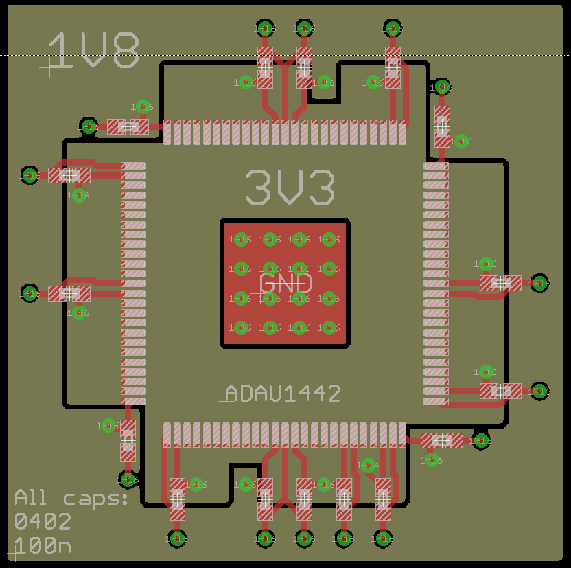
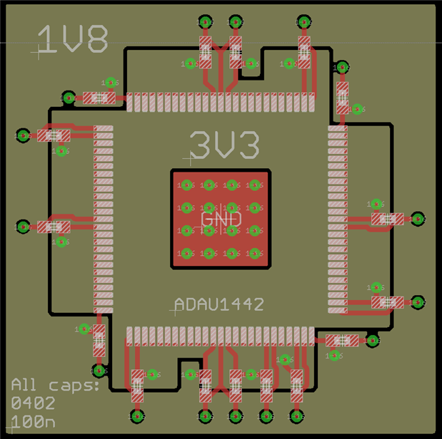
Hello Daniel,
Yes, you should probably switch the 1V8 and the 3V3.
The DVDD caps in the corners should have traces going directly to the DGND pins also on the corners. Then the trace out to the vias like you have done with the rest. So the IOVDD caps and the DVDD caps will both have a direct return path to the ground pin of the part.
So this is good what you are doing. It is a good start and the these are the most important parts to place first.
Dave T
Hi Dave
SOmething like this I suppose:
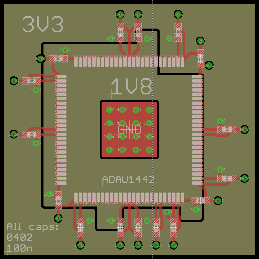
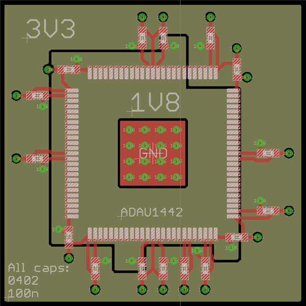
Hello Daniel,
Yes, Perfect!
Dave T
Please log in to reply.